Stainless-Steel Glass Elevator
Feb 1, 2021
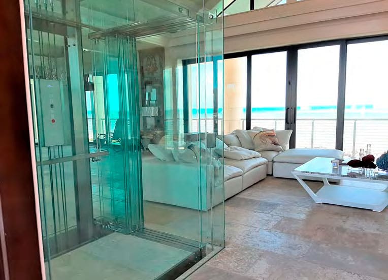
Teamwork and creativity overcome myriad challenges to deliver an aesthetically pleasing, robust system.
submitted by John Virk, UT Elevator
When contacted by an Arkansas-based architect designing a Florida Keys home, UT Elevator (UTE) felt the main challenge would be logistical, since the project was more than 1,600 mi.from company headquarters in Toronto. It rapidly morphed into a project much more complex — one that would test the full capabilities of UTE. As it turned out, the architect had come across an earlier Project of the Year article in ELEVATOR WORLD about UTE (“Mitered Glass Elevator,” EW, January 2016). “This is exactly what they’re looking for” is the phrase we remember. At the time, we did not know all the challenges the project had in store.
Upon initial building inspection and dialogue with the architect, it became clear that not just a custom glass elevator would suffice. It needed to be one that would withstand the extremely harsh, humid salt air and hurricanes of the region. Shortly after the project commenced in 2017, Hurricane Irma made landfall, with direct impact on the project site.
The house was built like a fortress, with more than 50 2-ft-tall piles driven into the bedrock below and concrete beams spanning the entire main floor. It quickly became evident that the elevator portion of the project would require our firm’s dedication to design a glass elevator and hoistway enclosure to meet not only aesthetics and ride quality, but also a new level of strength and durability.
To accomplish this, the project needed to be executed via five subprojects defined by our engineering and design teams:
- Cabin glass and glass fixtures: Cabin panels were safety rated with mitered corners for optimal views and assembled with custom hardware and a variety of glazing and adhesives. The car station was flush-mounted glass with capacitive touch buttons and an integrated hands-free phone.
- Structural assembly in 316 marine grade stainless steel and custom coated guide rails: Brushed, Blend “S” stainless-steel finish for the car and counterweight frames, rail brackets, machine bed plate and pit plate, and guide rails dipped and galvanized, then zinc- and powder-coated to match the stainless steel.
- Hoistway glass and stainless-steel structure: A two-level, all-glass hoistway integrated with the stainless-steel elevator support structure, along with an intricate array of embedded glass channels
- Underdriven glass doors: All metal components in 316 stainless steel, track assembly secured to hoistway glass with landing mechanisms mounted to custom-designed structural brackets attached to the building steel
- Variable-voltage, variable-frequency (VVVF) drive system and electrical routing, custom-built permanent-magnet drive machine with internal components coated in Armology TDC® and electrical power and signals routed via conduits embedded within the cabin and hoistway to keep them clear from view and protected from exposure
General weather protection involved modular, lower-level hoistway glass and a door designed to break away in the event of severe flooding. It also included an electrical subsystem in liquid-tight conduits with routing above base flood elevation; all electrical components are National Electrical Manufacturers Association rated 4.
Execution of each subproject relied heavily on cooperation between the developer and architect, and included a foray into video communication, computer-automated-design (CAD) and file exchanges over the cloud.
Cabin Glass
UTE specified the cabin to include four vertical panels and a single-pane glass ceiling. The vertical panels are approximately 7 ft tall with 45˚ mitered corner edges with cutouts to suit a flush-mounted, capacitive-touch glass car station, along with holes at the top of each panel to secure them to a welded frame above. Each panel is 13.5 mm, composed of two tempered 6-mm lights laminated together with a cured resin interlayer. Significant care was taken by our Concord, Canada-based supplier, Accura Glass Bending Inc., to ensure the panels remained flat during the tempering process and that the holes and cutouts were accurately aligned during laminating. This was to ensure minimal light distortion so that, when the panels were assembled, the 45˚ miters would be perfectly aligned. To achieve the miters, the panel edges were precision ground and polished to the final overall dimension.
Water-clear silicone was used to bond the panels to allow for vibration dampening and structural adhesion, while the panel assemblies were secured into embedded glass channels built into the cabin floor below and bolted onto the welded frame assembly at the top using a set of bespoke 8-mm glass standoffs with low profiles.
Glass Fixtures
Capacitive-touch glass fixtures were embedded into the control side glass panel for a uniform, flush appearance. The design posed numerous challenges and involved detailed communication and coordination with Italy-based fixture supplier Vega srl to fit all components into the allocated space. Custom latches were developed to secure the faceplate to the back box so the plate could be removed with a suction tool. All button contacts and our LED backlit logo needed to be compact in design. This process even involved visits to UTE in Toronto from Vega ownership and management.
Another key design challenge involved concealing the assembly and routing signals. Since the hoistway surrounding the system was full glass, the fixture assembly would be fully visible from all angles, and we were required to keep uniform material and lines intact. The solution included a set of finished stainless-steel plates bonded to the rear of the control panel glass to which the fixture control box was mounted. A custom-welded and polished stainless-steel rear cover with welded studs then cladded the control box and fit precisely to the dimensions of the front bond plates. The signal cable was then routed below the platform via a finely polished stainless tube.
UTE’s Greatest Production Challenge to Date
Moving from typical carbon to 316 marine-grade stainless-steel manufacturing presented a significant challenge to our team, resulting in a multistep process involving a variety of suppliers and a significant level of coordination and quality control. This included three separate fabricators (UTE included), two local polishers and onsite manual finishing in coordination with the general contractor.
The inherent challenge of fabricating stainless steel to a high-level finish additionally required the production team to move to a fully formed and fabricated methodology for the structural members in place of our standard structural c-channel and angle iron fabrication. This allowed for all parts to begin with flat plate steel laser cut according to CAD-modeled patterns and categorized by material thicknesses, which would, in turn, allow for the crucial and integral first bulk-polishing step. Each flat component was acid passivated prior to punching and fabrication, then followed a logistical and complex manufacturing process whereby parts were grouped via final geometries and their required production routing.
The only subassembly not glass or stainless steel were the guide rails, although the production process was equally challenging. To meet the project’s environmental-protection requirements, each guide rail underwent a multistep coating process starting with hot-dipped galvanizing, then zinc primer coating, and application of two layers of finish powder coating.
Hoistway Glass and Stainless-Steel Support Structure
The team envisioned a glass centerpiece on the main floor’s “great room,” which, when the elevator was present, would still provide a full and clear view of the ocean through the south curtain wall. Included in the centerpiece would be an artistically designed stainless-steel support structure that would both provide structural stability and complement the overall project. UTE developed the hoistway glass and steel support structure concept, then worked closely with the architect and general contractor to realize it.
The hoistway glass was manufactured with the upper level panels approximately 10 ft high X 6 ft wide for two of the hoistway walls and modular 10-ft-tall sections on the landing side to which the landing door system would connect. On the lower level is also a segmented glass façade entry system integrated with the lower-level glass landing door. There was a distinct challenge in handling and transporting the hoistway glass, as crates were custom made for both sets of glass, with the hoistway crate weighing approximately 1,500 lb. A particular challenge was having the glass manufactured in Toronto to very tight tolerances while providing enough flexibility to adapt to field conditions.
Detailed layout drawings and 3D models were created in-house to simulate site conditions. This allowed for nearly the full assembly to be digitally created and installed. The mock digital installation was imperative to the project’s success.
The intricate, stainless-steel, welded support structure began with a 1.5-in. solid pit plate pre-drilled and tapped to accept the elevator chassis structure. It then traveled up via 5-in. structural tubes 25 ft tall with angle brackets pre-welded to accept the rail brackets and chassis assembly. The crown of the structure was fondly referred to as “the halo.” It was designed to be multifunctional to secure the support structure to the building’s reinforced roof beam, and contain the glass channels to accept and position the large, upper-level hoistway glass.
Additionally, the lower level consisted of a steel-and-glass “break-away” vestibule, designed and built by UTE, extending past the glass hoistway façade. The break-away concept was specified by local building code in the event of severe flooding for a structure to “break away” so as not to transfer high loads to the building structure if items are not integral to it. The lower level landing door system was designed into the hoistway glass façade in a modular fashion as it, too, needed to be part of the breakaway system, should flood loading eliminate the door panels.
UDD Operator
Among the first companies in North America to implement the under-driven-door (UDD) operator for a glass elevator, we were confident in our adaptation of Fermator’s UDD solution for this project. We were required to be hands-on with the development of this system so the door components could be finished with 316 stainless steel and ensure proper modifications were in place to integrate with the glass hoistway. Constant coordination with the Spanish door supplier was challenging — yet rewarding — as its staff members were accommodating and thorough.
The car door features two laminated, safety-rated glass panels that are 17-mm thick, governed by the underdriven permanent magnet and VVVF integrated drive. The car door interacts with two glass landing door assemblies, each of which is attached to the building structure via custom-designed landing mechanism brackets built to support and adjust the full load and traffic load from below.
The complexity of the UDD door system required complete assembly and testing at our Toronto facility with electrical connections, parameter adjustments and door-panel adjustments made locally to allow for minimum onsite calibration. Assembly, disassembly, shipping and reassembly onsite created myriad challenges to ensure all adjustments remained intact upon arrival.
Integration of the car door operator with the cabin platform involved a significant degree of design modeling and local setup and testing. The overall chassis was offset toward the landing to balance the loading resulting from the heavy car door operator. Our design team developed an integrated welded stainless steel channel system to allow for modular assembly and positioning onsite.
Drive System and Electrical Subsystem
At the center of the drive system is a custom-built permanent magnet AC synchronous motor supplied by HIWIN Corp. Torque and speed settings were predetermined and internal components were coated with Armoloy® to guard against oxidation. A 2:1 roping system was used for loading efficiency to allow for the machine size to remain in line with the project’s view requirements. A variable frequency drive from KEB America supplies controlled voltage to the motor, as well as receives closed-loop feedback encoder signals. This system enables ride quality that matches the aesthetics.
One of the first tasks undertaken upon starting the project was determining the path for all signal cables to reach the required elevator components and lead back to the remote elevator controller. An intricate 3D conduit network was created digitally, then communicated to the general and electrical contractors via layout drawings. The general and electrical contractors then implemented the network during the initial construction phase. Multiple routes, which involved embedding PVC conduits into the main floor concrete and having them reach the landing door mechanisms and hoist machine via the structural support column, were required. This allowed for virtually no cables (other than the traveling cable) to be visible from the all-glass hoistway, a feat that required significant creativity. An added layer to the overall routing challenge was achieving the same level of cable and component concealment for the car’s electrical subsystem.
A True Team Effort
The project’s success relied heavily on close coordination among all members of the team, including the elevator manufacturer/installer, the general contractor and its subcontractors and the project architect. Production and engineering commenced with installation of the finished project at the forefront of the design. The UTE design team ensured all hardware was preassembled onto components (where possible) to ease installation.
As construction progressed, there would be repeated video call check-ins with field staff to relay adjustments or minor alterations that could potentially affect the elevator system. There were also three pre-planned field visits by UTE staff at predesignated project checkpoints. These visits allowed local production “go-aheads,’ also imperative to overall execution. The key solution to the challenge of supplying such a complex, integrated system was preassembly of nearly the complete system at UTE’s Toronto facility.
Logistics, Suppliers and Shipping
Arguably, the unspoken heroes of such complex projects are members of the logistics and shipping team who ensure all parts are ready, stored, protected and delivered to the site in a safe and efficient manner. With such a complicated array of participants, the logistics challenge not only stressed the company’s current methods, but allowed for a complete and effective overhaul to create a digital project-monitoring system.
As anticipated, the largest challenge we faced was having the glass cabin and hoistway panels produced in Toronto, the glass door system in Spain and having them reach the site and relative floor locations of the project in a timely and safe manner. To help achieve this, the UTE logistics team ensured that all glass materials were grouped into custom crates that would allow for proper handling and tracking.
A designated 52-ft tractor-trailer hauled all components to the site, where the general contractor and UTE’s field team received and unloaded the goods. Once again, the teamwork between UTE staff and the customer team ensured safe handling, removal and storage of all system components and set the tone for what would become the flagship project of our company. It was completed in March 2020.
Specifications
- System type: Gearless traction machine-room-less stainless-steel/glass elevator
- Drive: 2-hp permanent-magnet AC synchronous motor with closed-loop variable-voltage, variable-frequency drive control
- Door operator: Undercar-mounted, under-driven-door glass
- Travel, speed and capacity: 12 ft, 40 ft/min, 750 lb
- Composition: 316 stainless-steel, safety-rated tempered laminate glass
- Hoistway: Full glass panoramic, integrated stainless-steel support structure
Credits
- Developer: Lee Jackson Construction Inc.
- Architect: Terry Parker & Associates Architects
- Manufacturer and installer: UT Elevator Inc.
- Suppliers: Accura Glass Bending Inc.; ACLA USA Inc.; D&R custom Steel Fabrication; Draka-Prysmian; Fermator S.A.; HIWIN Corp.; KEB America, Inc.; Stella H; Vega SRL; and Vaughan Metal Polishing Ltd.
Get more of Elevator World. Sign up for our free e-newsletter.


