The ANZAC Museum
Feb 1, 2019
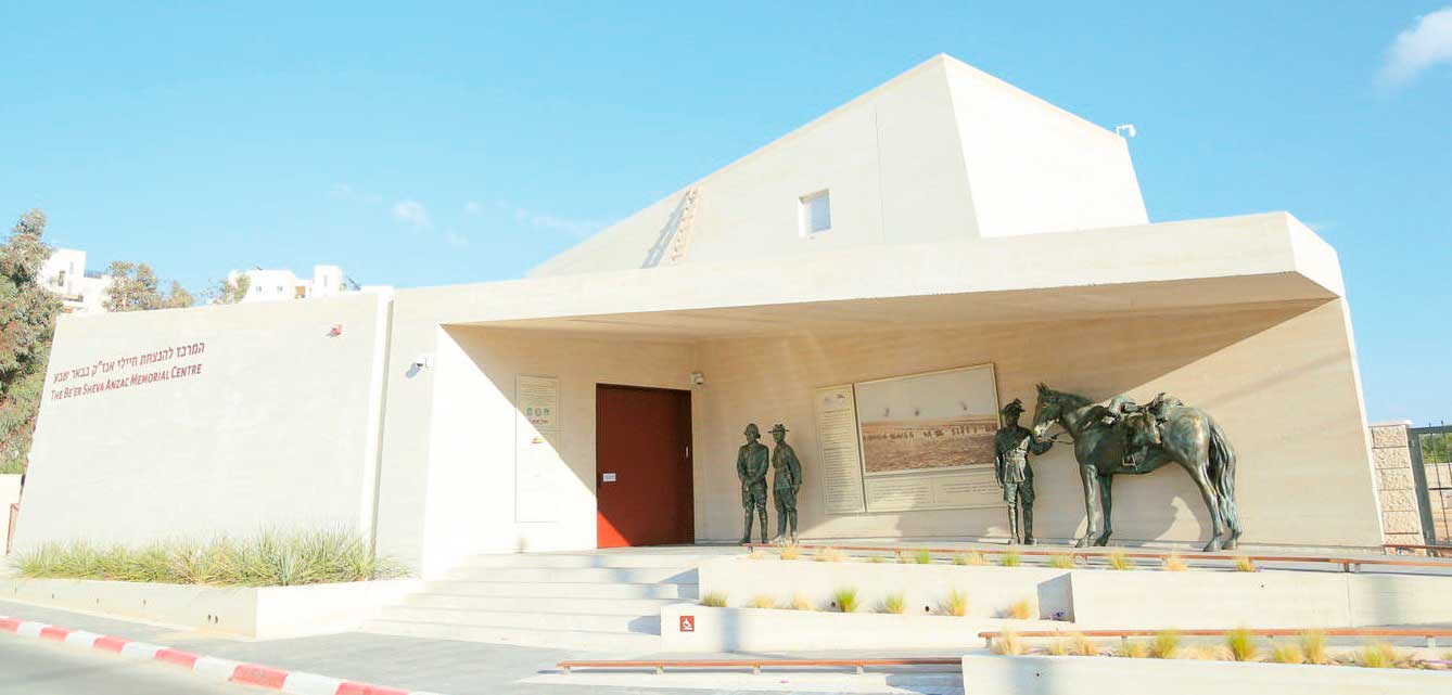
Electra Elevators meets the challenge of designing a rising multimedia theater for center commemorating important WWI battle.
In September 2016, I received a call from the Beersheba, Israel, mayor’s office, summoning me for an urgent meeting. It was a very brief meeting. When I arrived, they told me they had a short time to have the Beer Sheva ANZAC Memorial Centre museum open. The goal was to have the museum ready for an October 31, 2017, dedication to coincide with the 100th anniversary of the October 31, 1917, World War I (WWI) Battle of Beer Sheva, in which Australian and New Zealander soldiers of a light horse regiment defeated Ottoman defenders of the city in the Negev Desert.
The major feature of the museum was to be a 54-m2 room that rises very slowly, its motion unnoticeable and silent. The museum’s planners wanted an estimate from Electra Elevators, a part of Electra Ltd., for this device. Prior to this conversation, in a meeting with a local consultant and the Standards Institute of Israel, the planners were told Electra was the sole company in Israel with the ability to design, manufacture and install such a device within the required schedule.
I made my first sketches, contacted suppliers and prepared a cost estimation for the project. A few days later, my CEO and I met with the
museum planners for negotiation. We soon shook hands with our new customer and started the project, which we had 11 months to complete.
How It Works
The job was to design a room to be used as a small multimedia theater that is, in reality, a lift. Under the plan, the audience would enter the theater, which appears to be a room inside the museum. They would sit to watch a multimedia show, unaware that they were actually riding a very low-speed elevator taking them up to the second floor. When the show was over, they would exit the theater to an upper-floor terrace overlooking a cemetery for soldiers who took part in the battle, surprised they had ridden up with the room. It would be a stunning and memorable occasion for the museum’s visitors.
Technical Description
Hydraulic System
The first challenge was that the required speed of the elevator was 0.03 mps — 0.6 fpm. It was very difficult to find such a hydraulic system on the market; I tried many suppliers and got a lot of refusals before finding a suitable system. A major issue we sought to avoid was vibrations caused by slipping/sticking of the cylinder. Special seals provided by the cylinder manufacturer solved the problem.
I was hesitant about using one direct-acting piston below the platform but ultimately decided to keep it simple to enable a smooth and silent ride. We opted for a 1:1 direct-acting, below-platform hydraulic system. A variable- frequency drive for the pump was recommended by the manufacturer, as this would provide better performance for reduced noise.
Specifications of the hydraulic system:
- Piston diameter: 280 mm (11 in.)
- Rise: 6 m (20 ft.)
- Total load: 24 T.
- Speed: 0.03 mps (0.6 fpm)
- Motor/pump: 28 kW/260 lpm
Car Frame
The contract called for an open-top elevator and minimally exposed structural members as a means to maintain the surprise. We sought the help of an engineering company for the design of the platform and car frame.
A finite-element-method (FEM) model of the lift was prepared, followed by shop drawings, to match the visual requirements of the architect and the strict requirements of the elevator code.
Manufacturing and Installation
We manufactured the car frame in the workshop of the main contractor of the building, which is the owner of a steel-fabricating company. This decision significantly improved the coordination between contractors and helped to maintain the schedule, as the contractor was able to install the complete manufactured platform by crane, timed just before the closing of the building’s roof.
Pawl Device
We were asked by the local authorities to provide a safety system that would prevent the platform from falling in the event the lift system failed. We determined a standard unintended-car- movement system acting through the hydraulic valves would be very difficult to incorporate into the lift because of the very low travel speed. Our solution was a pawl-device system that activates as the elevator rises to the upper floor.
The pawl system uses four hydraulic cylinders mounted in each post of the platform, set to maintain a fixed distance between the rod in the floor and the stop elements, thus preventing the platform from resting on the stops. This also meant the lift operator would not have to raise the lift to disengage the pawls before lowering the platform to the bottom floor.
Guide Rails and Guide Shoes
To meet code requirements, the lift could have been installed with only two main guide rails, but we opted for four T140-3B rails. The load of the car was balanced by static load on the platform, because we knew the precise load position in the car. The audience would be sitting in fixed chairs, so the loads on the rails would be very small. The use of four rails provided redundancy and added ride stability. We chose roller guide shoes over sliding shoes because of the museum’s strict requirement for silence.
Safety and Operational Issues
Each wall of the elevator serves a special purpose. The entrance wall includes car door and landing door, the side wall has the car exit and landing doors, and the back wall is equipped with a huge special screen that enables a view of holograms beyond the lift on balconies in the shaft. For safety, we installed a partially transparent fence behind the screen made of special safety glass.
The holograms in the balconies inside the shaft require occasional maintenance. To allow workers to do their jobs safely, a feature of the control system brings the elevator to each balcony; in these instances, the glass fence functions as a barrier fence.
Meeting Code
Our goal was to comply with the EN 81-2 standard, because we wanted the lift to be inspected and certified by local authorities as an elevator, not as a special lifting system. With a few deviations, which were approved by the authorities, we met the code demands.
Coordination With Multimedia System
The interior of the car is a theater decorated in the fashion of a WWI bunker. For each cycle of the ride, the audience enters the theater and sits on chairs. As the doors are closed, a film begins, telling the story of the ANZAC Mounted Division’s role in the Battle of Beer Sheva (now called Beersheba) during WWI. After a few minutes of the film, the room arrives at a midrise point, where the hologram show plays for a few minutes. This is followed by a resumption of the film, during which the room rises to the top landing. Upon the ending of the film, the exit doors (opposite the entrance) open, and the audience f les out onto the terrace overlooking the graves of soldiers killed in the long-ago battle.
Having the show work properly requires precise coordination and timing between the multimedia and elevator controller. The system was tested, adjusted and rechecked until it all worked perfectly.
Opening Ceremonies
The museum’s goal was to have this multimedia show, housed within a unique elevator, ready for the grand opening on October 31, 2017, the 100th anniversary of the Battle of Beer Sheva. Electra Elevators designed, manufactured, installed and handed over the elevator on time, and the museum opening ceremony took place as scheduled. Many commanders of the Australian, New Zealand and Israeli armies, including Australian Prime Minister Malcolm Turnbull, New Zealand Governor General Patsy Reddy and Israeli Prime Minister Benjamin Netanyahu, participated in the ceremony.
Get more of Elevator World. Sign up for our free e-newsletter.


