The Humble Lift Counterweight
Dec 3, 2024
More than meets the eye
At first glance it appears that there may be little to be said in relation to the humble lift counterweight. However, recent failures in China, together with a few historical failures in the U.K., are a cause for concern.
A number of counterweight rope diverter pulley mountings have failed, due in the main to distortion and deformation of the counterweight top section horizontal members, which, as well as forming a critical safety element of the counterweight support frame, also retain the rope diverter pulley, shaft and bearings. As a result of such a failure, the diverter becomes detached from the counterweight with catastrophic consequences.
In a well-publicised failure at London’s Tower Bridge, a counterweight pulley and bearing which had been modified during a modernisation, became detached from the counterweight frame, resulting in injuries to passengers in the subsequent fall of the lift car.
Failures in China include a disintegration of counterweight fillers which are formed of an iron-ore powder and cement mix to the extent that the counterweight becomes unstable and/or fillers may be released with catastrophic consequences.
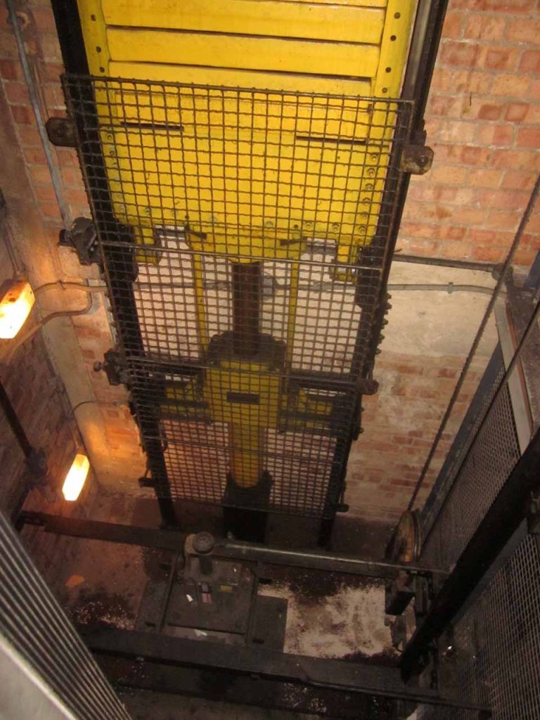
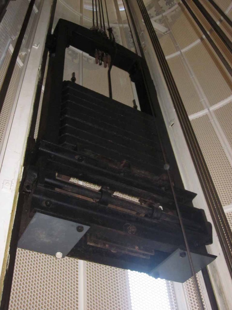
Traditionally, counterweights were formed as single or multiple piece cast iron units (Image 1) and later in welded or bolted structural steel frames with cast-iron filler weights.
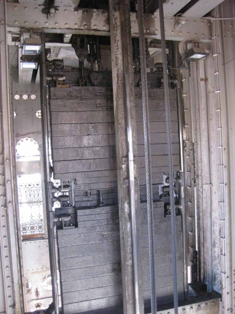
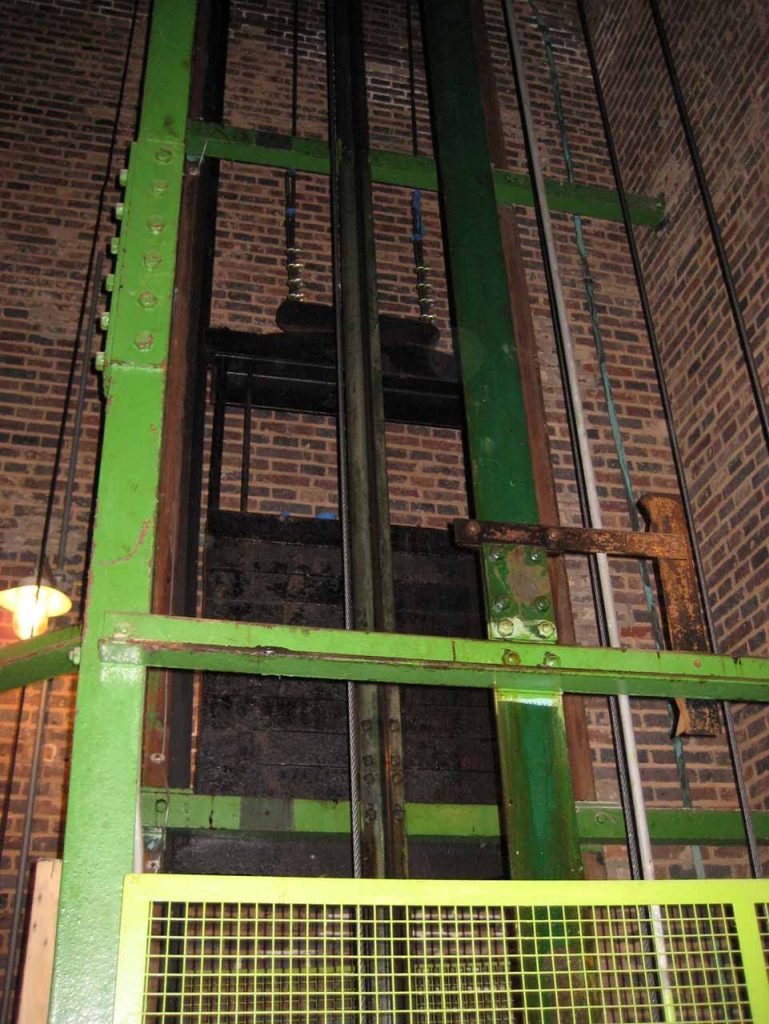
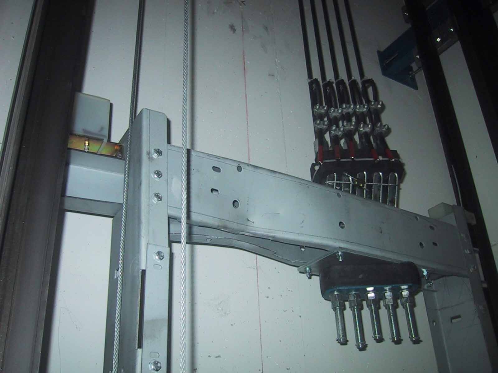
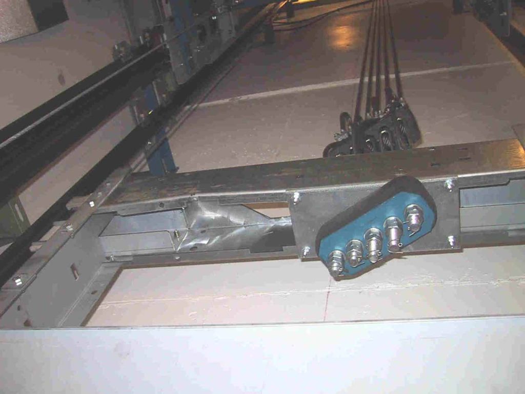
More recent counterweight designs incorporate frames formed of pressed sheet metal which can present particular problems in terms of handling during re-roping and repairs and in the susceptibility of the lightweight frame to damage and distortion. Image 2 shows a modern counterweight frame with the top section distorted due to improper slinging and lifting with a sling having been wrapped around the upper frame members. Image 3 shows the same counterweight after the original damaged sling members had been replaced and where a further slinging and lifting process resulted in the deformation of the newly replaced top section in a different failure mode. Whilst the engineers in question had not been provided with the manufacturer’s slinging and lifting instructions or specialist lifting anchors, albeit that they were subcontracting to the lift manufacturer, there seems little or no excuse for replicating the error twice in succession.
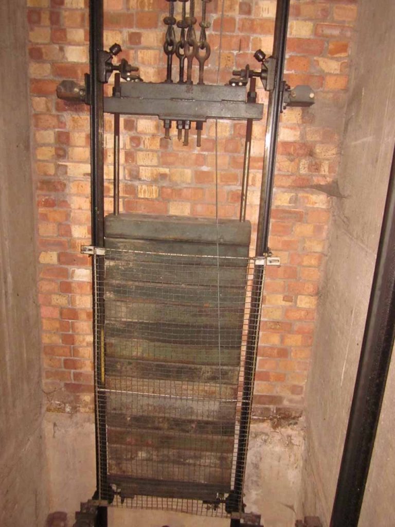
A consideration of the loads and forces which may be applied to a counterweight is reflective of a more complex component assembly than may be initially apparent. Clearly a counterweight must be able to withstand the forces arising during normal use, including the loads imposed by the counterweight frame itself and its associated filler weights, those arising during buffering at overspeed; the forces applied at the rope termination as the lift car accelerates and is raised by the suspension ropes; forces arising due to the attachment of compensation and compensating frames, together with the additional forces to be absorbed and transferred through the compensation to the pit structure during car safety gear engagement; and anti-rebound operation and additional loads imposed where the counterweight buffer is mounted upon the counterweight rather than on the pit floor (Image 4). Where counterweight safety gears are deployed, the counterweight must be designed to safely withstand the forces imposed during safety gear operation at up to 125% contract speed and such that the counterweight and its components remain intact and secure. The counterweight frame must be sufficiently rigid as to ensure that the counterweight remains constrained within its guide rails and should not break free and collide with the lift car. In high-speed applications, the balance of the counterweight must be considered and may be achieved through adjustment of the extent of any offset in filler weights and/or the positioning of these within the frame and/or by fine adjustment of the location of the counterweight suspension rope anchorage.
All of these factors and potential hazards must be accommodated and mitigated in the design of the counterweight such that the counterweight is, in reality, a complex engineering product assembly requiring serious consideration in any design.
A rule of thumb in traditional design practice, provided that a counterweight should be configured to accommodate an additional 5% of the estimated car mass and space for not less than 10% of the overall estimated car mass, or at least two additional fillers.
All of these factors and potential hazards must be accommodated and mitigated in the design of the counterweight such that the counterweight is, in reality, a complex engineering product assembly requiring serious consideration in any design.
The question of the car-to-counterweight balance ratio or percentage overbalance often arises in industry discussion and is often unnecessarily complicated by suggestions of an absolute requirement for a 50% overbalance, which is, of course, incorrect. I have encountered an overbalance as low as 33%, and so long as the traction relation is maintained within Standard, this is fine. It is the particular lift design and application which dictates the percentage overbalance, and the Standards provide no absolute requirement in this respect. It is for the designer, considering the particular characteristics of the lift design and application, to determine. It is the design capacity of retained original equipment which renders it so important that, as part of any modernisation, the appropriate overbalance, rather than just a guess at 50%, should be established.
The application of the Safe Lift concept dates from the 1920s and involves the provision of a counterweight extension which is retained in the lift pit. When required, the extension is connected to the underside of the counterweight in order to facilitate the transport of a heavy load, in excess of the normal lift car SWL. I recall one design which was provided to facilitate the transport of a large transformer from the roof of a factory for repair/renovation. The transformer was the heaviest piece of plant in the factory and during original design and construction the designers included the Safe Lift concept in order to facilitate maintenance and repair of the transformer. The carrying capacity of a lift car could be increased by up to one-third by way of Safe Lift application.
The use of double counterweighting dates from the latter part of the 19th Century and the loads imposed by the car and its car counterweight are carried on an overhead pulley system which is separate of the drum drive lift machine and which is connected separately, by its own ropes, to the lift car and to its own load counterweight. This arrangement reduces loads on the drum lift machine and machine bearings. Image 5 shows an example which dates from 1907 and remains in regular service to this day.
Tie-rod type counterweights were widely used through the early part of the 20th Century and continued through EN 81-1: 1998, albeit restricted to car speeds below 1.0 m/s, until the final exclusion of the design in EN 81-20: 2014. An example is shown in Image 7. Whilst the retention of tie-rod designs in modernisation is not recommended, many modernisation designs incorporate modifications to such counterweights involving the addition of securing frames or similar safety provisions.
We should also recognise and understand that counterweights are long-lived components which are more often retained as part of a lift modernisation such that a counterweight may be in service for 50 years or more. Indeed, I am aware of a counterweight which dates from 1908 and which has now been in service for 116 years complete with its timber guide rails shown in Image 6.
Whilst the development of lightweight pressed metal counterweight frames and alternative filler materials is often justified by way of sustainability factors and “Green” credentials, the reduced service life of these components when compared with traditional designs together with the introduction of increased safety risks (increased loading of pressed metal frames during modernisation for instance, together with questions of fatigue life) leads me to question the long-term viability and value of such cost-reduced (or value-engineered) components.
Get more of Elevator World. Sign up for our free e-newsletter.
