Universal Design Principles for Cabs: Accessibility
Apr 1, 2021

An examination of standards on cabs the author says should be followed to help make lifts accessible to all
There has been an effort to “converge” the EN 81-20 and -50 (ISO 8100 Parts 1, 2 and 3) European standard with the North American ASME A17.1/CSA B44 in recent years. Convergence had the goal of removing barriers to trade by creating a global prescriptive standard that would be equivalent around the world. It is a lofty and desirable goal.
It looks like current “performance-based” European standards will play an active role in the writing of worldwide codes for elevators. One of these standards is about accessibility to lifts for all, EN 81-70, which officially came into force in many countries in 2018. This article will begin by examining the current legislation on it.
Accessibility entails enabling all passengers, including the disabled, to benefit from elevators equally and independently. Universal design principles reject the division of the human population into able-bodied and disabled people. The next part of this article is a summary of the latest updates and developments considering the above-mentioned standard, especially regarding cabs and cab accessories.
Contrast
Contrasting colors — most importantly, contrasting tones — should be properly used for object identification and danger avoidance. Contrast is the difference of reflection between two surfaces; for example, 100% contrast is black and white, because a lusterless black surface absorbs all light (0% reflectivity), while a white surface reflects all light (100% reflectivity). The car floor and panel walls, the operating panel and the wall on which it is installed and the buttons and button panels should be supplied in contrasting colors.
Entrances: Door Openings
The landing and car doors shall be automatic, power-operated and horizontally sliding. The clear opening width shall be at least 800 mm for type-1 cars; 900 mm for type-2, -3 and -4 cars; and 1,100 mm for type-5 cars. In existing buildings, the clear opening width shall be at least 800 mm for type-2 cars.
Car Dimensions
The inside dimensions of cars with a single entrance, or with two opposite or two adjacent entrances, shall be chosen in accordance with Table 1. Car dimensions shall be measured between the structural car walls. Decorative finishes on each wall that reduce the minimum car dimensions given by Table 1 shall not exceed 15 mm in thickness.
Equipment Inside Car
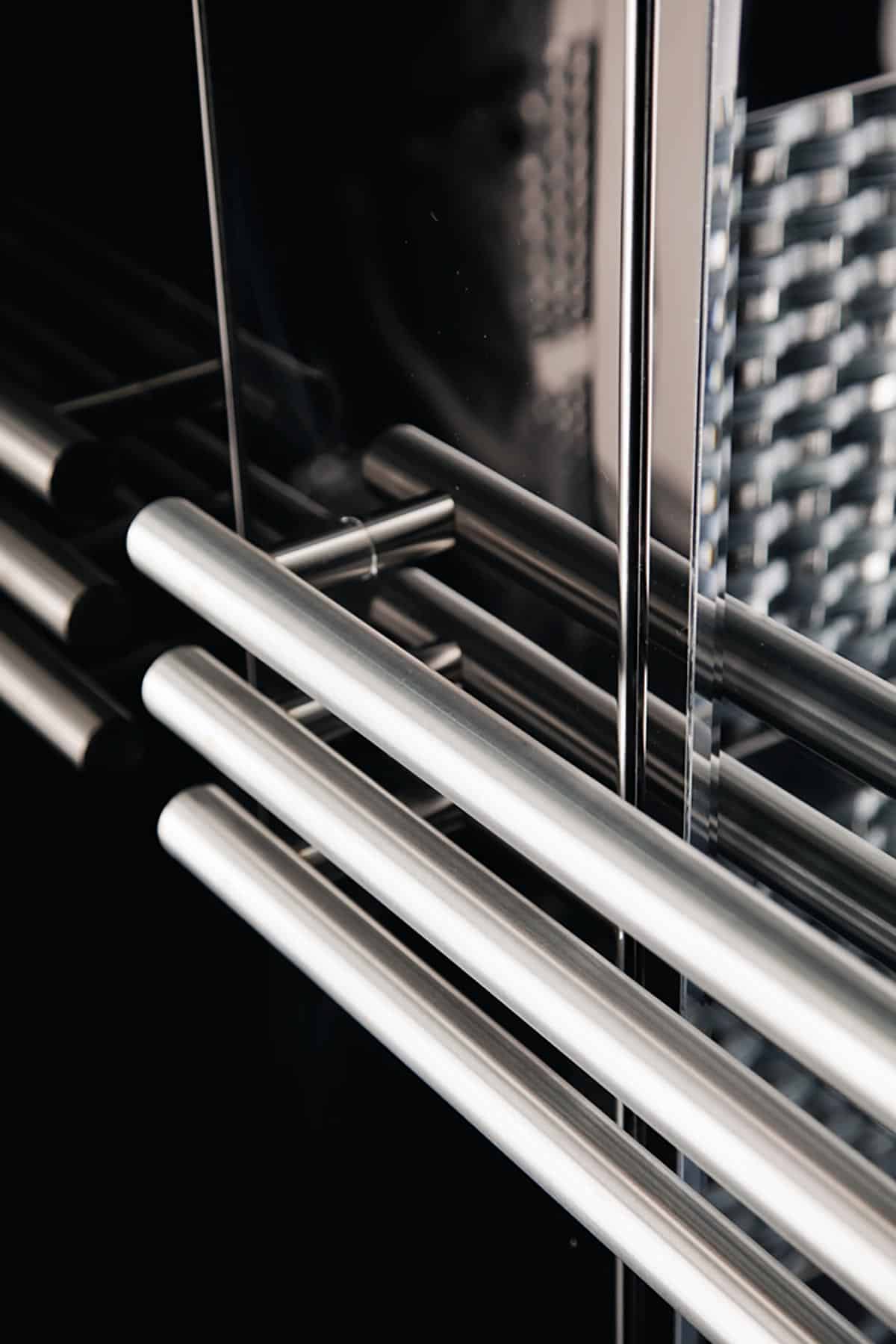
A handrail shall be installed on the side wall where the car operating panel (COP) is located as follows:
- The handrail shall be interrupted where the car operating panel is located to avoid obstructing control devices.
- The handrail may only be installed on one side of the COP if the shorter side would not accommodate a handrail with an overall length of at least 400 mm.
- The gripping part of the handrail shall have cross-sectional dimensions between 30 and 45 mm with a minimum radius of 10 mm.
- The distance between the wall and gripping part of the handrail shall be at least 35 mm.
- The height of the top edge of the gripping part of the handrail shall be 900 mm ± 25 mm from the finished floor level.
- The ends of the handrails shall be closed. Where there is a risk of collision with the projecting ends (e.g., where the handrail is interrupted in front of the COP), the handrail shall return toward the wall.
- For car types 1, 2 and 3, the handrail may be installed on the opposite side wall if the handrail would restrict the car entrance width. For car types 4 and 5, a second handrail shall be installed on the opposite side wall or rear wall.
There shall be no additional features attached to the car walls below a height of 800 mm. The reason for this is that it may restrict the accommodation and turning of passengers using wheelchairs or walking aids (Figure 2).
|
Type of Car |
Minimum Car Dimensions |
Accessibility Level |
Building Type/Usage |
Remarks |
|
1 |
Car width/depth: 1,000/1,300 mm (450 kg) |
This car accommodates one wheelchair user without an accompanying person. |
Shall only be used in existing buildings where building constraints do not permit the installation of a type-2 car |
Type-1 provides only limited accessibility for persons using a manual wheelchair or an electrically powered class-A wheelchair. This type also provides accessibility for persons using walking aids (e.g., a walking stick) and for persons with sensory and intellectual disabilities. |
|
2 |
Car width/depth: 1,100/1,400 mm (630 kg) |
This car accommodates one wheelchair user and an accompanying person. |
Shall be the minimum size for new buildings |
Type-2 provides accessibility for persons using a manual wheelchair or an electrically powered class-A or -B wheelchair.This type also provides accessibility for persons using walking aids (e.g. walking sticks, crutches or rollators). Passengers with wheelchairs are unlikely to be able to turn around in this type of car and must leave it moving backward. |
|
3 |
Car width/depth: 1,100/2,100 mm (1,000 kg) |
This car accommodates one user with a class-C wheelchair and some other passengers. It also allows transport of stretchers. |
Recommended sizes for cars in public areas (e.g., outdoor facilities, stations, etc.) and for cars where the transportation of class-C wheelchairs shall be provided |
Type 3 provides accessibility for persons using a manual or an electrically powered class-A, -B or -C wheelchair. It also provides accessibility for persons using a manual wheelchair with a tractor unit. When cars of this type are configured with two opposite entrances, this can provide straight-through circulation from the main entrance to different floor levels. |
|
4 |
Car width/depth: 1,600/1,400 mm or 1,400/1,600 mm (1,000 kg) |
This car accommodates one wheelchair user and a few other passengers. It also allows the wheelchair to be rotated within the car. |
Shall be the minimum size for cars with doors on adjacent walls* |
Type 4 provides accessibility for persons using a manual or an electrically powered class-A or -B wheelchair. It provides sufficient space for most wheelchair users and for passengers with walking aids. |
|
5 |
Car width/depth: 2,000/1,400 mm or 1,400/2,000 mm (1,275 kg) |
This car accommodates one wheelchair user and several other passengers. It also allows a wheelchair to be rotated within the car. |
Type 5 provides accessibility for persons using a manual or an electrically powered class-A, -B or -C wheelchair. It provides sufficient turning space for persons using class-A or -B wheelchairs and for persons using walking aids (e.g., walking frames, rollators, etc.). |
For car types 1, 2 and 3, a device (e.g., a small mirror) shall be installed to enable passengers to observe obstacles behind them when moving backward out of the car. (Passengers with wheelchairs are unlikely to be able to turn around in this type of car.) If a glass mirror is used, it shall be laminated per EN 81-20.
The car floor shall be slip-resistant. The same material used in the lift lobbies may be used for the lift car floor.
Control Devices and Signals
Car Control Devices
The COP shall be located on the side wall as follows:
- With center-opening doors, it shall be on the right side when entering the car from the main entrance side.
- With side-opening doors, it shall be on the closing jamb side when entering the car from the main entrance side.
- With a car width that exceeds 1,600 mm, it shall be provided on both side walls of the car.
- In the case of cars with adjacent doors, a COP shall be provided on each car wall that does not have a door.
Minimum lateral distance between the centerline of any button to the corner of any adjacent walls shall be 400 mm. (Figure 3)
Car Signals
A position signal shall be located within or above the COP. The centerline of the signal shall be positioned between 1,600 mm and 1,800 mm from the finished floor level. The height of the floor numbers shall be 30-60 mm.
Guidance for Increased Accessibility and Usability
The following items may be considered for improving the accessibility and usability of lifts:
- Glass landing doors should be marked to avoid confusion caused by transparent materials and allow the lift entrances to be easily identified. The same marking used for walls and doors in the building may be used here.
- Transparent elements in walls of the car and hoistway or in the landing and car doors may reduce the risk of panic. In the case of entrapped passengers, support communication with others outside the lift. However, transparent elements may also exacerbate anxiety associated with fear of heights.
- The height of the landing and car doors and the clear height of the car should be at least 2,100 mm.
- Handrails should be installed on all car walls without doors.
- Walls should have matte surfaces to prevent reflections, optical confusion and glare caused by the reflection of light sources. There should be a minimum vertical distance of 300 mm between the floor and bottom edge of the mirror.
These items may be particularly important in such facilities as train stations, hospitals and nursing homes, where passengers with higher degrees of and/or combinations of disabilities should be able to use the lift.
References
[1] EN 81-70:2018 Safety Rules for the construction and installation of lifts – Particular applications for passenger and goods passenger lift – Part 70: Accessibility to lifts for persons including persons with disability
[2] EN 81-70:2003 Safety Rules for the construction and installation of lifts – Particular applications for passenger and goods passenger lift – Part 70: Accessibility to lifts for persons including persons with disability
[3] EN 81-20:2020 Safety Rules for the construction and installation of lifts – Particular applications for passenger and goods passenger lifts – Part 20: Passenger and goods lifts
[4] EN 12183:2014 — Manual wheelchairs. Requirements and test methods
[5] EN 12184:2014 — Electrically powered wheelchairs, scooters and their chargers. Requirements and test methods
[6] The International Association of Elevator Consultants. “Should ASME A17.1/CSA B44 ‘Converge’ with ISO 8100?” (2018).
Get more of Elevator World. Sign up for our free e-newsletter.


