What manufacturers and architects should be aware of in the planning stages of a building’s elevatoring
Elevator contractors are quite familiar with their specialty tasks – they do sales engineering, negotiate and sell elevators, produce shop drawings, procure materials, install elevators and carry out maintenance. However, the background information (i.e., how a vertical-transportation solution is selected for a new building project) and the factors that govern elevator selection (i.e., how the original elevator layout and specifications came into existence) remain somewhat hidden. This article provides an insight into understanding the essential design efforts that go behind the vertical-transportation planning of any new construction project. It also intends to help architects formulate a scientific method of developing, integrating and verifying a vertical-transportation system design within their projects.
It is hoped the information presented in this article will also help elevator contractors understand tender specifications and drawings in a better way and be informed and decisive, while complying with or deviating from a project requirement. It is also intended to help elevator contractors properly estimate their costs and liabilities on a new project and present attractive value engineering options to their clients, while increasing their chances of winning a project.
Applicable Codes
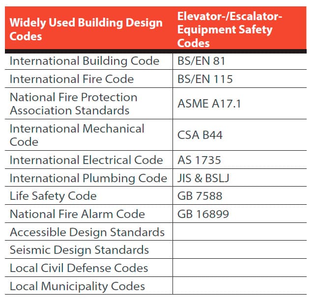
There are applicable building-design codes for projects based on their geographical location. These include (but are not limited to) international-building, life-safety, fire-protection, seismic, accessibility and local-municipality/civil-defense codes. While these are mandatory requirements, the consultant and/or owner might choose to exceed the minimum requirements and provide additional/superior features, such as evacuation communication systems, evacuation elevators, etc.
Performance Targets
Any new project has owner requirements, and most established brand owners have their own vertical-transportation design and performance requirements. Design requirements include average interval, average waiting time, average time to destination, car capacities, and car and door sizes. While starting a new design project, consultants should check with the owners for their published design guidelines. If this is not available, the consultant should propose standards based on the international best design practices and the project’s brand positioning at the geographical location. This becomes the “design criteria” for the project.
Analyzing Population and Vertical Circulation
For each type of building project, the population and vertical circulation of people and material inside the building must be elaborately studied. This includes types of users, populations on each upper floor, parking spaces on parking floors, loading docks, arrival/exit patterns, access-control concepts, bulk arrival (including transportation for both the public and staff) scenarios, interfloor circulation patterns and peak traffic estimation. Main lobby floors should be identified for arrival. Exit scenarios and the volume of peak traffic should be estimated using practical and working knowledge on each building type. Similarly, high-traffic floors that are not main lobby floors should be identified, and peak traffic to/from these floors is to be estimated.
Traffic Segregation
To realize the elevator systems’ maximum efficiency, it is ideal to have dedicated elevator groups for each user type. It also helps in improving user comfort, access control of protected areas and exclusivity for VIP users. However, it may not be economical or viable commercially. With this in mind, the conditions that will allow combining certain user groups are to be reviewed, and minimum required elevator groups (cores) should be proposed. Once this is agreed upon, the peak traffic is again verified for the combined user types (if any) for each elevator core.
Elevator Sizes/Capacities
Depending on user space requirements, comfort levels and various code requirements, the most suitable car sizes/capacities and door sizes should be identified for each elevator group. Even though an elevator analysis might minimally require smaller elevators, an architect might select larger elevators to serve the above requirements. The option to provide a machine room at the top of the building should also be discussed with an architect in reference to machine-room-less (MRL) elevators, which may have different capacities, speed and range.
Elevator Traffic Analysis
Various traffic patterns and peak traffic identified throughout the day at the building can now be analyzed via calculations or a simulation. A typical elevator traffic analysis involves assuming various elevator operating parameters (door times, passenger movement times, acceleration, etc.), and such assumptions must match desired car and door sizes. All such assumptions made at this stage must be practically achievable by any elevator manufacturer for the traffic study results to be valid.
It is very important not to overestimate or underestimate the peak traffic, because this will ultimately result in more or fewer elevators. It should also be noted that the estimated average waiting times are only indicative and cannot be repeated on an actual site. Hence, practical knowledge and an exceptional understanding of simulation procedures are necessary for a vertical-transportation consultant to properly guide the architects/design team.
Various speed, capacity and quantity combinations should be verified to check if the performance meets the design criteria, while keeping in mind the initial and maintenance costs for each combination. Vertical dimension requirements (e.g., pit depth, overhead and machine-room height) should be simultaneously considered, because the required vertical dimensions cannot be provided due to various architectural reasons and height restrictions. After careful evaluation, the ideal and acceptable elevator groups are to be selected.
Core Dimensions
Once the elevator groups are finalized, elevator core sizes should be planned in such a way that they accommodate at least three elevator manufacturers available in the local market and per the applicable equipment safety codes. Special requirements (to accommodate such circumstances as building plumb deviations, seismic designs, fire-rated entrances, wind-shear noise, piston effects, special safety features, etc.) should also be considered, and the core sizes increased as necessary. Type of construction for the elevator core walls is then finalized, considering the structural and fire-code requirements.
For quick reference, all the elevator groups should be consolidated onto a spreadsheet showing all relevant dimensions and specification data. This spreadsheet could be used as a cross-reference, while verifying the elevator tender response for the project. Elevator contractors are required to confirm their compliance or noncompliance to each item on this summary sheet.
Core Layout
Based on the final core dimensions, the elevator cores should be laid out on the plan drawings. Structural support requirements for the guide rails, separator beams, trimmer beams, entrance frames, machines and controllers should be identified, and suitable provisions should be made for the size and type of construction. Door structural openings should be approximately shown on the plans. It is important to note that the location of door structural openings and front-wall dimensions are approximate. This must be finalized and constructed based only on the elevator supplier’s shop drawings.
Machine-Room Layout
For each elevator core, the machine-room layout should be finalized, taking the requirements for easy access and safe working conditions into consideration. Machine-room heights include joist beams/lifting hooks for maintenance. For heavy machinery, where possible, a trap door should be included on the machine-room floor in order to drop the machine to a floor with elevator service, then move it to the ground floor for future maintenance/replacement. For MRL elevators, the location of an emergency rescue panel outside the hoistway should be identified.
Structural Coordination
The structural loads on the guide-rail support system, impact loads on the pit buffer, reaction loads at the machine room and lifting-hook capacities should be reviewed, and the structural frame (reinforced cement concrete (RCC) beam/column/slab/wall) should be designed to meet the requirements. The structural fixing (anchoring) requirements for the guide-rail brackets, machines and other steel elements should be reviewed, and a suitable substructure (RCC or similar) should be provided. The size of structural door openings, trap doors and rope holes are to be compiled, and their impact on the structural stability of the core wall system should be reviewed by the structural design engineers.
Mechanical Coordination
The mechanical requirements for efficient functioning of the elevator equipment should be reviewed, and suitable provisions should be made by the mechanical designers to remove the heat generated by the elevator equipment and provide suitable ambient conditions within the machine room. These provisions can include heating, ventilation, air-conditioning, ducting, routing and diffusers. Special requirements, such as air-conditioning for the elevator car, pressurization, stack effect, smoke mitigation and noise reduction requirements should also be reviewed, and a matching mechanical design and additional equipment provided to prevent any detrimental effect on the elevator systems’ performance. Acoustics and vibration characteristics of the elevator equipment should be reviewed, and suitable coordination and adjustments may need to be carried out to reduce such undesirable effects generated by the elevator system.
Electrical Coordination
The electrical requirements for efficient functioning of elevator equipment should also be reviewed, and suitable provisions (suitably rated isolators, fuses, fire protection, and cable sizes, shields, routing and containment) should be made by the electrical designers to supply the power required by the elevator equipment. Standby-power requirements should be identified for specific elevators and suitable provisions made in this stage through automatic transfer switches to provide generator power to specific elevators, as well as other building services. The requirement of a battery-operated automatic rescue device and regenerative drives for specific elevators should then be reviewed and finalized. Equipment sensitive to electromagnetic interference (EMI) at the site should be identified, and the elevator power-supply circuits should be suitably designed to prevent EMI with such equipment.
Lighting Coordination
Normal lighting requirements for the machine room and emergency-lighting requirements should be reviewed. Suitable lighting fixtures can then be provided to achieve desired brightness inside these spaces. Special elevator-car interior lighting and lighting effects should be reviewed and incorporated.
Plumbing Coordination
Sump pits required within the elevator pits should be reviewed and suitable provisions made for the sump pits (i.e., a permanent sump pump, simple floor drain or dry sump pit). Drainage piping design, routing and containment should be reviewed, so they do not cause a code deviation and damage elevator equipment. Special floor drains required at each elevator lobby should be evaluated and adopted if found necessary.
Low-Voltage-Systems Coordination
Special features and low-voltage systems linked to the elevator equipment should be reviewed and suitable cabling with containment, power supply, mounting requirements and location of interface terminals coordinated with relevant vendors. The systems in question can include remote monitoring, remote control, building management, access-control card readers, closed-circuit TV cameras, media displays, external dialing means, fire alarms and smoke detectors.
Architectural and Interior Design Coordination
Related elevator spaces (shaft, lobbies and machine rooms) should be reviewed in parallel with the interior design concepts and appropriate alignments carried out. Suitable lobby widths are necessary to achieve international standards in user comfort. Elevator-door handing (which side they open) is to be reviewed in relation to the surroundings and elevator approach, after which the most suitable should be selected. Depending on the front-wall cladding thickness and floor-finish thickness, suitable adjustments can be made to the architectural positioning of each door opening.
Special attention should be paid to aligning the elevator-door openings opposite to each other. Placement of hall-call stations, lanterns, indicators, firefighters’ switches, emergency control panels (for MRL elevators only) and related equipment regularly installed at the landings should be reviewed, adjusted and aligned to achieve the best-looking lobby possible.
Signalization and Signage Coordination
The following is a list of required signalization/signage that requires coordination with the elevator-installation procedure:
- Car and landing call stations
- Lighting color
- Faceplate color and material
- Visual/audible signals
- Automated voice messages
- Media display schemes
- Accessibility and VIP features (on push buttons and signalization)
Accessibility Design Coordination
Every passenger elevator should be reviewed for compliance with accessibility codes and features. Elevator car sizes that allow full rotation of wheelchairs, auxiliary car control panels for the handicapped, maximum height of push buttons from floor level, and Braille and tactile features on push buttons are examples. Special accessibility features such as induction loops for the hearing impaired, voice announcements in the local language and tactile pavements in the elevator lobby may be reviewed on a case-to-case basis and adopted as deemed necessary.
Tender Documents
Traditionally, manufacturers estimate their tender price based on the elevator specifications (and elevator drawings, if any). However, it must be noted that elevator specifications always cross-reference various other specifications within the master specifications. It is recommended that elevator manufacturers read all relevant codes and specifications to understand how the elevator system is required to coordinate and work with other project equipment and design concepts.
Conclusion
While the information in this article should help architects to exercise a fair amount of control on vertical-transportation system design and integration, a qualified and knowledgeable vertical-transportation engineer is the only suitable person to completely manage and control the process in the best possible manner. The author and his firm welcome any query from the readers of this article on any vertical-transportation system design and will be pleased to offer engineering guidance.
Get more of Elevator World. Sign up for our free e-newsletter.