VF Drives
Feb 1, 2014

Humans have made use of elevators for centuries, but real advances were not possible until the introduction of the electric motor. There had been water-hydraulic-powered elevators, and before them, human- and animal-powered machines. Even if we could ignore the humanitarian implications, it would be hard to imagine that these arrangements would work in the context of today’s big-city high-rise applications.
Learning Objectives
After reading this article, you should have learned about:
♦ Why the electric motor dominated elevator applications
♦ The relative advantages of DC and AC motors
♦ How synchronous and asynchronous motors compare
♦ The basic parts of a variable-frequency (VF) drive
♦ How to use a multimeter to troubleshoot a VF drive
Then, there was steam. Heated water vapor, however, was just the medium; there still had to be a source of power. Wood or coal had to be obtained (still by human and animal means), then transported before it could be fired. In contrast, the electric motor at the turn of the 20th century, was a clean, quiet, compact engine. It nearly always performed as expected without protest, its energy arriving at the site via two or three slender metal conductors.
At first, there was no AC. DC was available from chemical batteries that would be deemed very inefficient by today’s standards. Sufficient electrical power was available to permit early experimenters to build prototypical DC motors, but they were adequate only for demonstration projects and as scientific curiosities. Very little useful work could be performed but never enough to lift an elevator car off the ground. Viable electric motors had to await the development of real-time power generation with a distribution system. The first of these systems was pioneered by Thomas Edison. Initially, Edison was motivated to power homes and businesses, primarily so they could have lights. To this end, he built the first of many localized distribution systems in lower Manhattan. He improved on existing DC dynamo technology, enabling the availability of much more power.
Because DC power cannot be easily transformed (that is, stepped up or stepped down), AC quickly eclipsed DC as the dominant power protocol. Soon, AC motors, transformers and three-phase technology surfaced. The AC induction motor appears to have been independently invented by Galileo Ferraris and Nikola Tesla. It became dominant because of its simplicity and economical construction. It is estimated that 90% of the AC motors currently in service are induction (asynchronous) machines.
The new AC motors (especially induction types) were, in some ways, greatly superior to their DC ancestors, because the commutation was external, a result of the cyclical nature of the AC power supplied by the utility. The DC motor, on the other hand, required internal commutation in order to work. This was provided by the brush/commutator combination, which is an elegant situation, since it introduces the magnetizing current into the spinning rotor, while periodically reversing the polarity of that current as needed so the rotor’s magnetic field can interact with the static magnetic field produced by the energized stator. But, since the brush/commutator combination is electromechanical, it is subject to wear and requires maintenance. The labor and material costs in the life of the DC motor are significant, especially if brush maintenance is neglected so there is damage to the commutator, which often involves a motor teardown and machine-shop work.
Synchronous AC motors run at a speed precisely determined by the frequency of the line voltage, the only other factor being the number of poles per phase. The formula is NS = 120f/P, where NS is the synchronous speed of the motor, f is the frequency of the AC supply at the motor input terminals, and P is the number of magnetic poles per phase.
Notice that P is in the denominator of the expression on the right side of the equation, so the more poles incorporated into the construction of the motor, the lower the operating speed. At 60 Hz, common shaft speeds are 3,600 rpm for a two-pole motor, 1800 rpm for a four-pole motor, 1,200 rpm for a six-pole motor, 900 rpm for an eight-pole motor, 720 rpm for a 10-pole motor and 600 rpm for a 12-pole motor. These values could be reduced by adjusting the supply voltage, but that would not be a good way to regulate the speed, because it would be equivalent to loading the motor more heavily, bringing it closer to a stall condition. The result would be more heat and shortened motor life. The correct way to regulate the speed of an AC motor is to alter the frequency, and this was not a practical option until many decades after the invention of the AC motor, when the VF drive came on the scene.
The induction motor’s shaft speed is also dependent on the line frequency, but it is not precisely synchronized to the electrical input, and for this reason it is known as an asynchronous motor. The shaft speed is always less than the synchronous speed by a certain amount, and this relationship, expressed as a percentage, is known as “slip.” There are two important things to remember about slip. First, it is not some wasted or lost energy that is the result of an inferior design. Secondly, it is not a phase lag as in a reactive electrical load. Because of slip, the induction motor’s rotor actually turns slower than the rotating magnetic field produced by the stator. What makes the inductive transfer of power from the stator to the rotor is the difference in speed between the two, so if the rotor speed were to catch up with the speed of the stator’s rotating magnetic field (if the slip were to be reduced to zero), there would no longer be a transfer of power, and the motor would not turn. For this reason, a zero-slip situation for an induction motor is impossible. The more the rotor is slowed by means of an increasing load, the greater the torque, up to the point where the magnitude of the load causes the motor to stall. There is an equilibrium involving load, speed, torque and slip at all times. Large induction motors at full loads may have more than 1% slip, while small motors typically have a slip closer to 5%.
The induction motor, though inexpensive and easy to maintain, was not suitable to power elevators and other loads that required smooth speed regulation in infinite increments for many decades. For these applications, the DC motor continued to fill the need. Brush/commutator maintenance was commonplace. To power DC motors from an AC supply was never a major impediment. A rotary converter, vacuum tube or solid-state rectifier would suffice, and this could realistically be considered part of the cost of running a DC motor.
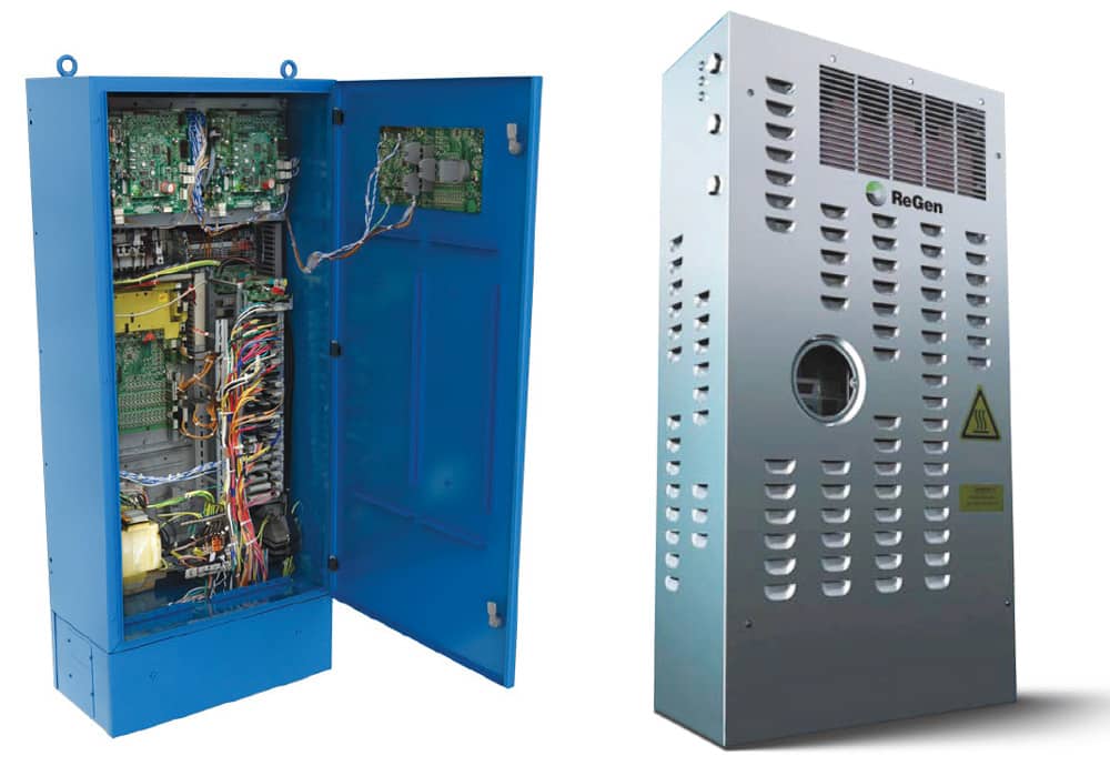
All of this changed when the VF drive came into use. This ubiquitous piece of equipment is also known as “variable-speed drive,” “adjustable-speed drive,” “adjustable-frequency drive,” “AC drive,” “microdrive” and “inverter drive.” These terms are essentially synonymous, except for the fact that those including the word “speed” may also refer to non-electric or hydraulic systems. The VF drive includes the rectifier, DC bus and inverter, together with user interface and supplementary overcurrent protection (if any) and various other accessories. The term may or may not be used to include the motor.
As we have seen, the speed of an AC motor, either synchronous or asynchronous (induction) is dependent upon the frequency of the power supplied to the motor terminals. From this, one may correctly conclude that it is possible to regulate the motor’s speed by changing the frequency. This is what happens in a VF drive. A VF drive can be connected to any AC motor (synchronous or induction) and used to control its speed, although there are some limits that must be observed:
- Since many AC motors incorporate an internal cooling fan, when the motor is run at reduced speed under load, it will experience temperature rise due to diminished heat dissipation. This tendency can be mitigated by supplying external air or liquid cooling, or by taking steps to reduce the ambient temperature, either by air-conditioning or by ventilating the machine room.
- Running a motor faster than the rated speed can make for shorter bearing life.
- The VF drive can produce an output that deviates from the perfect sine wave AC motors thrive on. Primitive electronic inverters produced a square-wave output, which would cause the AC motor to overheat. Additionally, due to the fast rise and fall times in the waveform, there would be power-quality problems that would affect other equipment within (and even outside) the facility where the inverter was housed.
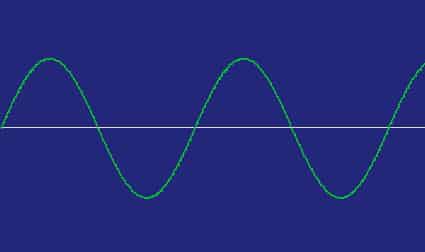
A perfect sine wave is a consequence of the circular nature of a rotating generator. An examination of a graph showing the voltage level (vertical axis) plotted against time (horizontal axis) reveals the essence of the sine wave: the rate of change of the voltage is greatest when the voltage is least (closest to zero) and least when the voltage level is greatest (closest to negative/positive poles). Trigonometrically, the electrical output of a spinning rotor will be a sine wave, because the sine of an angle is the side opposite it over the hypotenuse of a right triangle. This is generated by a rotating vector.
Over the years, the electronic (as opposed to rotary) AC inverter has improved so that its output more closely approximates a pure sine wave. This has been good news for the AC motor, because it has become possible to regulate its speed by varying the frequency at the motor’s input terminals without creating harmful harmonics and electromagnetic interference.
A motivation for using a VF drive is to reduce electrical consumption, while enabling the user to conveniently start and stop the motor, reverse its direction, control speed and perform other modifications to the operation of the motor. Any of these commands can be automatically initiated, and it is possible to program and monitor parameters and view diagnostics.
When called upon to start a motor, the VF drive typically supplies power at reduced frequency and voltage. There is not the high in-rush current seen in a motor that has direct on-line starting. Once the motor begins to turn, voltage and frequency are ramped up at a smoothly controlled rate until operating speed is attained. This procedure provides substantial energy savings if there are frequent starts. Additionally, there will be less wear experienced by mechanical and electrical components. The same logic applies to stopping the motor, where smooth ramped deceleration can provide benefits.
Additional power-usage and machine-wear savings accrue when operation at a reduced speed is an option. For example, the VF drive for a ventilation fan could be programmed to operate at a lower speed when the ambient temperature drops below a specified level or when the equipment is less active, either of these conditions causing less heat.
Another motivation for using a VF drive is when variable speeds are needed for the intended application. An elevator motor is required to operate at more than one speed, and smooth ramped transitions are desirable. VF drives are used, in these situations, and they are far superior to outmoded gearbox or multiple-pulley solutions.
A VF drive with operator interface provides useful diagnostics that, in case of malfunction, can inform the technician of the cause and show suggested remedies. The alphanumeric readout will display an error code. The operator’s manual, usually supplied as part of the original installation, will provide the key. If this manual is missing, it should be available as a free download from the manufacturer’s website. It is suggested that, as part of the preventive-maintenance program, copies of the correct manual be available in each machine room and filed in the maintenance shop.
Not counting the motor as part of the drive, the VF drive has the principal sections that comprise the power train. The front end consists of a full-wave rectifier, which is necessary for an AC-to-AC VF drive. (There is also such a thing as a DC-to-AC VF drive, which is used when the electrical supply is DC, as in a solar photovoltaic system.) The usual setup is three-phase input and three-phase output powering a three-phase induction motor, although occasionally, single-phase equipment is used, and sometimes the motor is synchronous (non induction) for specialized applications. A half-wave rectifier could be used, but it would make less-efficient use of available power, and the output would be more difficult to filter.
The second stage within the drive is the DC bus. Two heavy conductors convey the rectified power. A part of this stage consists of one or more capacitors shunted across the DC bus. Since a capacitor offers far greater impedance to DC than to a fluctuating voltage level, the capacitor serves its purpose of filtering out ripple that would otherwise be prominent in the rectifier output. To help in this process, an inductive coil may be inserted in series within the DC bus. The objective is to obtain pure DC. The less ripple in the DC bus, the better the system will perform.
The DC bus feeds the inverter stage, which contains six solid-state devices configured as three parallel connected strings, each composed of two of the devices connected in series. The three-phase output going to the motor is carried by three conductors, each connected to the midpoint of one of the series strings. Notice that the device configuration and wiring of the inverter stage closely resemble those of the rectifier stage. If the VF drive is visualized as symmetrical, with three current-carrying lines at its input and three current-carrying lines at its output, and the DC bus is in the middle, troubleshooting using a multimeter and/or an oscilloscope will be greatly simplified.
The solid-state devices may be enclosed in a module or be discrete components with substantial heat sinks. At one time, the semiconductor devices were silicon-controlled rectifiers, but since the mid 1980s, the insulated-gate bipolar transistor (IGBT) has become the usual component in the VF-drive inverter stage. These ubiquitous active devices are characterized by very high input impedance. They draw infinitesimal current and, therefore, are virtually invisible to the control circuit.
Great care must be exercised in handling the IGBT, since it can be destroyed by static charge in the technician’s body or an ungrounded tool. Replacement devices of this sort are often shipped packed in conductive foam so the leads, poked into the foam, are shunted together and not able to acquire a static voltage difference. They should be kept in this packaging until installation.
The wiring arrangements of both rectifier and inverter stages make checking the active components straightforward. First, survey all power terminations (input, output and at the motor) for looseness or corrosion. Visually inspect them to see if an active component (capacitor or inductor) appears burnt or distorted. Input voltage should be uniform for all three legs (with not more than a 5% difference) and certainly not a dropped phase. At the motor, when powered down, there should be uniform DC resistance among each pair of legs and very high megohm resistance of each leg to ground.
To check the VF drive components, power down the unit. Remember that large electrolytic capacitors may hold lethal electrical energy long after the equipment has been disconnected from the power source. Do not work on the VF drive unless you know how to bleed and measure such voltage.
If your multimeter has the “diode check” function, it is better to use this mode, because it measures the actual voltage drop (rather than a pseudo resistance) with the ohmmeter providing bias. Connect the negative multimeter probe to the positive DC bus. Then, touch the positive probe successively to each of the three input terminals. If you see a small forward-bias voltage drop between each leg and the positive DC bus, then so far, so good. Next, reverse the probes. If you see the same forward-bias voltage drop, this part of the VF drive is good. A short will indicate that the rectifier has one or more defective diodes. If you read an open, look for an open charge resistor. If this preliminary procedure indicates a problem, individual components should be checked.
The output stage is checked in a similar manner. Connect the positive probe to the negative DC bus, and touch the negative probe, in turn, to each of the output terminals. Look for a forward-bias voltage drop. Then, touch the negative probe to the positive DC bus and the positive probe to each of the output terminals. Again, look for the forward-bias voltage drop. If you read a short, the inverter stage is faulted. An open would indicate inverter damage or a blown DC-bus fuse. If that is the case, it is better not to just throw another fuse at it and hope for the best. There is a high probability a fault caused heavy current flow, and the fuse protected other components from damage. The best approach is to make every effort to pinpoint the underlying defect. To check the bus capacitor(s), do an ohm check between positive and negative bus conductors. You should not see a short.
More-advanced tests can be done with an oscilloscope. First, look at the input: power-supply problems can cause poorly formed sine waves or harmonics that may damage equipment facility wide. Then, look at the voltage on the DC bus: it should be a nice, clean DC with no significant ripple. If there is an AC component on the DC bus, the inverter stage will not function properly.
Learning-Reinforcement Questions
Use the below learning-reinforcement questions to study for the Continuing Education Assessment Exam available online at www.elevatorbooks.com or on p. 95 of this issue.
♦ What advantages do induction motors possess?
♦ What are the two functions of a commutator in a DC motor?
♦ Which two factors determine the speed of a synchronous motor?
♦ Why is “slip” necessary for an induction motor?
♦ Why is a VF-drive/motor combination cheaper to run than a straight AC motor?
Look at the voltages at the inverter output or motor terminals. The sinusoidal pulse superimposed on the much-higher frequency-carrier wave, when connected to the highly inductive motor load, makes for a sine-wave current that should vary as required to regulate the speed of the motor.

Get more of Elevator World. Sign up for our free e-newsletter.


