Alternative Weightless Testing: An Overview
Sep 1, 2012

Alternative weightless testing methods and the future of elevator testing in North America
There have been many discussions about alternative weightless testing methods for periodic load tests on elevators taking place in the North American elevator industry. Various opinions from different sectors of interest are discussing the future of elevator testing in the U.S. and Canada caused by a number of proposed revisions to ASME A17.1/CSA B44: Safety Code for Elevators and Escalators. In addition to the revisions, Canadian authorities take part with high interest in these discussions, since most provinces in Canada have adopted the joined North American and Canadian Safety Code for Elevators and Escalators, and therefore, will require load testing for elevators in the near future.
The main questions concerning alternative weightless testing include:
- Could the required periodic Category 5 load tests be acceptably replaced by an alternative weightless testing method, while retaining public safety?
- How reliable and safe are existing alternative testing methods?
This article will provide detailed information on the function and capabilities of an existing weightless testing system, called ADIASYSTEM®, to help understand the reasoning behind decisions of authorities from countries abroad to permit the use of such an alternative testing system as an equivalent method for periodic elevator load tests.
The most important part of the article addresses one of the most criticized parts of alternative weightless testing – the Category 5 test for car safeties. The physical fundamentals and function of ADIASYSTEM to perform this test for Type B Safeties with an empty car will be explained. The article will also introduce two further tests for electric and hydraulic elevators, which could be performed by the ADIASYSTEM to increase the safety of an elevator.
Category 5 Test for Type B Car Safeties (Progressive Car Safeties)
The function and stopping distance of safeties is described and required in Point 2.17.3 of ASME A17.1-2010/CSA B44-10 as follows: “The safety device, or the combined safety devices, where furnished, shall be capable of stopping and sustaining the entire car with its rated load from governor tripping speed (see also 2.16.8).” Furthermore, for type B safeties shall pertain that they “stop the car with its rated load from governor tripping speed within the range of the maximum and minimum stopping distances as determined by the formulas in. . . ”
It is important to point out that the stopping distance is the consequence of deceleration caused by the application of the car safeties. Because of this coherence and other advantages (e.g., the possibility of testing with less than rated speed for high-rise elevators), a direct measurement of decelerations during the application of the car safeties and a verification against defined maximum and minimum limits is more suited than the assessment of stopping distances through a measurement of slide markings on the guide rails. Furthermore, the knowledge of decelerations with regard to hazardous effects for an individual in the car is more significant and meaningful than stopping distances. This is one reason why the European Harmonized Standard EN 81-1:1998+A3:2009: Safety Rules for the Construction and Installation of Lifts –- Part 1: Electric Lifts defines limits of decelerations instead of distances. Point 9.8.4 of EN 81-1 requires: “For progressive safety gear, the average retardation in the case of a rated load in the car shall lie between 0.2gn and 1gn.”
The worst-case scenario for the need of the application of Type B car safeties is that a freefalling car with its rated load has to stop and sustain on the guide rails within defined maximum and minimum deceleration (stopping distance) limits. To simulate a freefalling car of an electric elevator with a traction machine and counterweight, the counterweight can have no influence on the deceleration of the car safeties during its application. To prevent the influence from the counterweight, and, therefore, to get the real conditions of the car during a car safeties test, higher decelerations of the car are desired. This is only possible through minimizing the kinetic energy of the car. That means, if the test will be performed with an empty car, the kinetic energy is much less than it is with a rated load; therefore, the deceleration is much higher and the stopping time and distance is shorter, all causing the counterweight to jump and not influence the test.
As a consequence, ADIASYSTEM measures the existing decelerations of an empty car traveling down during the application of the car safeties without the influence of the counterweight. After, the system calculates the measured decelerations of the empty car into decelerations of the car with its rated load based on the characteristics of type B safeties. ASME A17.1-2010/CSA B44-10 Point 2.17.5.2 defines type B safeties as “Safeties that apply limited pressure on the guide rails during the stopping interval, and which provide stopping distances related to the mass being stopped and the speed at which application of the safety is initiated.” Figure 1 shows the coherence between the breaking force “FB” and the breaking distance “s” (force – distance diagram) of a type B safety. It is important to note that after a specified distance (needed to completely apply the safety), the “FB,” which is applied on the car, is constant until the car has been stopped and sustained on the guide rails.
Based on this information, the calculation from the measured deceleration of an empty car aempty to the deceleration of the car with its rated load aRL is easy to perform when the mass of the car mcar is known (see Formula 1).

ADIASYSTEM consists of a data logger called ADILOG USB affixed atop the elevator car directly to the car frame to collect deceleration data during the test. ADIASYSTEM software is used to transfer the data via USB interface from the data logger to a PC and displays the collected data in diagrams. The entire test can then be verified and evaluated through the graphs in the diagram. If the average deceleration during the application of the type B safeties is within the defined maximum and minimum limits, the car safeties are still meeting the requirements, and the test was successfully performed under real freefall conditions and with an empty car. All results, including parameters and measurements, can be saved, stored and used to prepare a test report.
Increase Elevator Safety through Alternative Testing Methods
ADIASYSTEM, as an alternative weightless testing, offers various tests to increase the safety of elevators in a time-effective and sparing way.
Traction Test for Electric Elevators
The traction test for electric elevators is a simple test to verify and evaluate the traction of an electric elevator under consideration of the actual suspension-member construction, the type and amount of lubrication (as applicable), the material and the conditions of the sheave and the suspension members with an empty car. The results provide information of the present traction value and safety margins and, therefore, allow an accurate technical statement if the traction between the suspension members and groove or contact surface of the traction sheave is still sufficient.
To perform the traction test, ADIASYSTEM uses an electronic force meter gauge attached to one suspension member through a hook and connected with a belt and pipe to a support point (fixed point), such as the hoistway ceiling or machine frame. Figure 2 shows the measurement setup for the traction test on an electric elevator with traction sheave.
The theoretical fundamentals for the approach of measurement and calculation are simple. The force “F” in one suspension member is the sum of the Force Fcar initiated by the mass of the empty car, divided by the number of suspension members “n” and the test Force “Force” initiated by manually turning the traction sheave and holding the suspension member against the support point (Figure 3).
The ADIASYSTEM software is connected with the electronic force-meter gauge during the test and calculates the actual traction based on the physical coherences and specific elevator parameters, such as the number of suspension members, as well as the weight and suspension type of the car. It quantifies the traction reserves for the suspension member with the most unfavorable traction.
Test of the Anti-Creep Leveling Device for Hydraulic Elevators
ADIASYSTEM makes it possible to verify the correct function of the anti-creep leveling device (re-leveling device), which is used on hydraulic elevators to automatically correct a change in car level caused by leakage or contraction of fluid in the hydraulic system (as defined in Point 1.3 of ASME A17.1-2010/CSA B44-10). The test is performed with an empty car and based on physical pressure measurements and calculations to provide exact information regarding whether the hydraulic-elevator drive system is capable of automatically re-leveling the car with rated load. An electronic pressure gauge is connected online to the ADIASYSTEM software and used to record a pressure-time behavior of a complete cycle of an empty car traveling from the highest to the lowest landing and back, and calculates hydraulic losses and efficiency. Another part of the test is the application of the pump relief valve, which is needed for the final calculation. Based on the dynamic and static test results, the ADIASYSTEM software allows the exact statement if the anti-creep leveling device is functioning correctly and the elevator is capable to re-level with rated load in the car.
Summary
The purpose of ASME A17.1/CSA B44 is to provide the safety of life and limb and promote the public welfare. This statement should be the basis for all discussions about alternative weightless testing methods and the future of elevator testing in North America. Therefore, the only acceptable way to allow alternative elevator-testing technologies is to ensure an equivalent or higher level of safety is provided by the application of an alternative testing system.
The explanations of functions and capabilities of the ADIASYSTEM, developed and patented by TÜV SÜD, should help one better understand why alternative-testing systems are already permitted in other countries. There are various benefits of such a computer-aided system, (such as calculated test results based on simple physical fundamentals and sound engineering, proper documentation to meet quality assurance requirements and traceability, and time and cost efficiency in use). This system allows an equivalent or higher level of safety, and the experience of more than 15 years shows that ADIASYSTEM is a reliable and safe alternative weightless testing system for elevators.
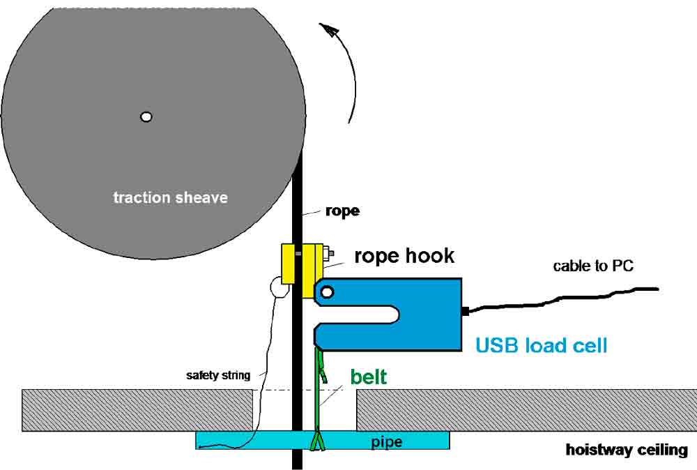
Figure 2: Measurement setup for the traction test with ADIASYSTEM 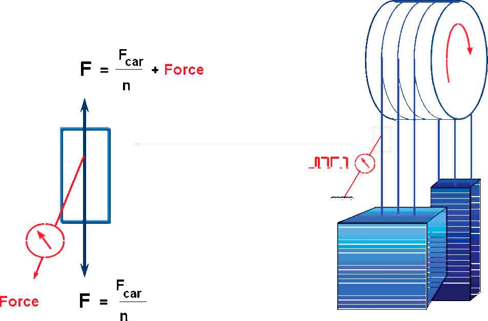
Figure 3: Physical fundamentals for the traction test with ADIASYSTEM 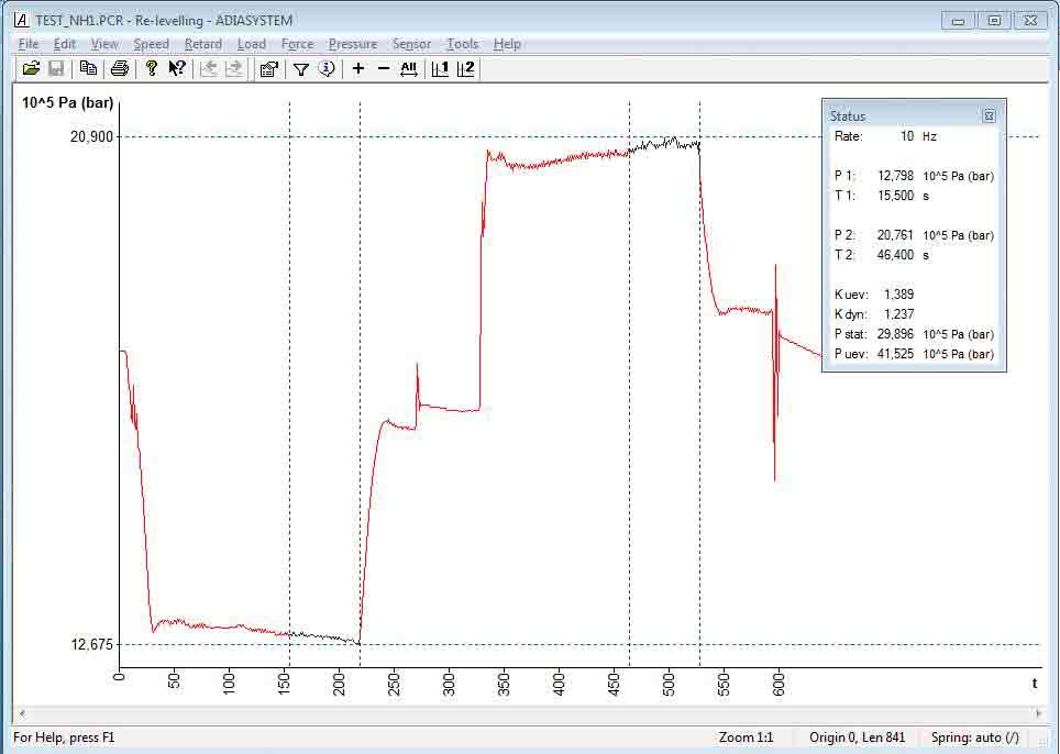
Figure 4: Diagram for the anti-creep leveling device test with ADIASYSTEM 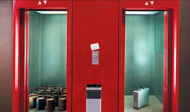
Figure 5: (l-r) Test equipment for conventional testing and alternative weightless testing with ADIASYSTEM
Get more of Elevator World. Sign up for our free e-newsletter.


