Designing Elevators for Universal Accessibility
Sep 1, 2025

A global perspective
by Muharrem Bilge Çakırer
Elevators are no longer just vertical carriers; they are essential infrastructure for equitable mobility. Modern accessibility is not a courtesy, but a codified engineering requirement, reinforced by global standards like ISO 8100-7. As demographics shift and expectations rise, elevators must accommodate a wide spectrum of users, including those with permanent or temporary impairments. The challenge is clear: design systems that are not only compliant, but intuitively inclusive.
1. Introduction: Why Inclusive Elevator Design Is No Longer Optional
With more than 1.3 billion people globally living with disabilities (World Health Organization, 2023) and growing numbers of users navigating cities with strollers, canes or luggage, elevators must evolve into inclusive mobility systems. No longer luxury features, accessibility elements are essential for independence, equity and compliance. Yet, implementation often falls short — either by oversight or misinterpretation. This article examines how elevator design can go beyond minimal legal standards to proactively serve real-world user diversity.
2. Global Standards for Accessible Elevators
Accessibility is now a recognized civil right in international building regulations. Key standards shaping elevator design include:
- EN 81-70:2022 (EU): Defines minimum requirements for accessible elevators — car size, controls, signage and support elements
- ISO 8100-7:2024 (Global): Aligns EN 81-70 with global norms; poised to become the first legally binding international accessibility standard for elevators by Muharrem Bilge Çakırer
- Americans with Disabilities Act (U.S.), BS 8300 (U.K.), JIS T9251 (Japan): Address local accessibility needs, with varying emphasis on spatial planning, control placement and user guidance.
Rather than simply complying, designers must understand the intent: enabling independent, safe and dignified vertical mobility for all.
3. Accessibility Equipment in Cars
3.1. Accessibility Button
An accessibility button shall be provided and marked with the international symbol for Provision for the Disabled (ISO 4190 5:2006, Table C.1, No. 10). It shall allocate a car adjacent to the relevant control device or alternately shall extend the door-dwell time of the allocated car. It may also activate additional features like extended time to place a call assignment of the call to a larger car, etc., where appropriate.
3.2. Accessible Touchscreen Interfaces
Touchscreens shall provide accessible interaction via an “Accessibility Button,” which activates acoustic menus and extends interaction time. Symbols must be at least 25 mm high and offer visual, tactile or audible feedback. These features support users with visual or motor impairments and are defined in Annex C of ISO/DIS 8100-7.
3.3. Alarm and Emergency Signaling Systems
Accessible elevators shall include both audible and visual alarms. Visual signals shall use flashing yellow or green indicators, while audible alarms shall emit a bell or speech signal. These alerts shall remain active until manually deactivated or acknowledged.
3.4. Voice Annunciation Systems
All accessible elevators shall include an audible announcement system to indicate floor arrival inside the car. The sound level should be adjustable between 35 and 65 dB (A) under normal conditions and may be increased up to 80 dB (A) in noisy environments such as transit stations or airports. The sound pressure level should be adjustable by authorized personnel only.
3.5. Mirror
While not strictly required by law, mirrors play a crucial role in elevator accessibility. For users in wheelchairs, mirrors enable rear exit maneuvers without assistance — especially in cabins with only a front door. Mirrors also serve a psychological purpose by alleviating claustrophobia and making small elevator cabins feel more spacious. Their inclusion is a recommended design best practice in enhancing both functionality and user comfort.
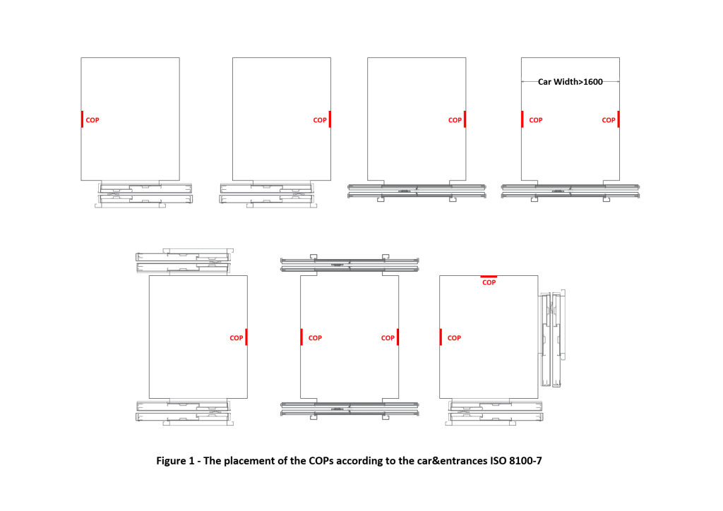
3.6. COP
The location of the Car Operating Panel (COP) shall accommodate a wide range of user needs, including wheelchair users. Proper positioning depends on the elevator door configuration:
a) In center-opening door systems, the COP should be placed on the righthand side as the user enters the car.
b) In side-opening (telescopic) systems, it shall be installed on the side of the closing edge of the door.
In all cases, a minimum lateral clearance of 400 mm (15.75 in.) shall be maintained between any COP button and the adjacent corner of the car wall to allow unobstructed approach and operation.
As urban demands grow and technologies evolve, elevator design must shift from mechanical utility to human-centered solutions.
Positioning the COP on the front return wall directly adjacent to the door opening is strongly discouraged. For wheelchair users or those with limited range of motion, this location poses significant access challenges and may render the controls unreachable. Therefore, such placement is considered noncompliant with universal design principles and accessibility standards.
Contrary to common belief, the decision to install a second COP inside the car is not determined by the car’s depth, but by its width. Per ISO 8100-7, Clause 5.4.2.3.5 (c), if the internal car width exceeds 1,600 mm (63 in.), a COP shall be installed on each of the two side walls.
For cars with adjacent entrances (dual-entry configurations), a COP should be installed on every wall that does not contain a door. This ensures optimal accessibility regardless of approach direction.
The requirement for one or two COPs in cars with opposite (through-type) door configurations depends on the door opening direction:
- If both doors are center-opening, two COPs shall be installed — one on each side wall — regardless of car width.
- If the doors open toward opposite sides (i.e., telescopic but in reverse), a single COP is sufficient, provided the car width does not exceed 1,600 mm.
However, if the car width is greater than 1,600 in such a scenario, dual COPs are required to ensure operability from either side.
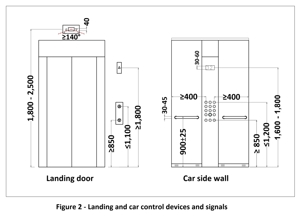
3.7. Handrail
Per ISO 8100-7:2024, clause 5.3.2.1, every elevator car shall be equipped with at least one handrail. This handrail should be installed on the wall where the COP is located. To avoid obstructing access to buttons and indicators, the handrail shall be interrupted at the section corresponding to the COP and its ends must curve toward the wall to minimize injury risk during sudden stops or user falls.
If the wall where the COP is installed is too short to accommodate at least 400 mm (15.75 in.) of continuous handrail, the handrail may be installed on only one side of the panel. The gripping surface of the handrail shall have a diameter between 30 mm (1.18 in.) and 45 mm (1.77 in.), with a minimum radius of 10 mm (0.39 in.). A minimum clearance of 35 mm (1.38 in.) shall be maintained between the handrail and the wall surface.
The height of the upper edge of the gripping surface should be 900 mm (35.4 in.) ±25 mm (0.98 in.) above the finished floor level. If two stacked handrails are used, this height requirement applies to the uppermost handrail. No fixtures shall be placed below 800 mm on car walls, as they may obstruct wheelchair users’ maneuverability, particularly in Type 1 and Type 2 cars.
According to ISO 8100-7, in car Types 1, 2 and 3, if the handrail restricts the clear entrance width, it may be mounted on the wall opposite the COP. This exception is especially relevant in narrow shaft configurations.
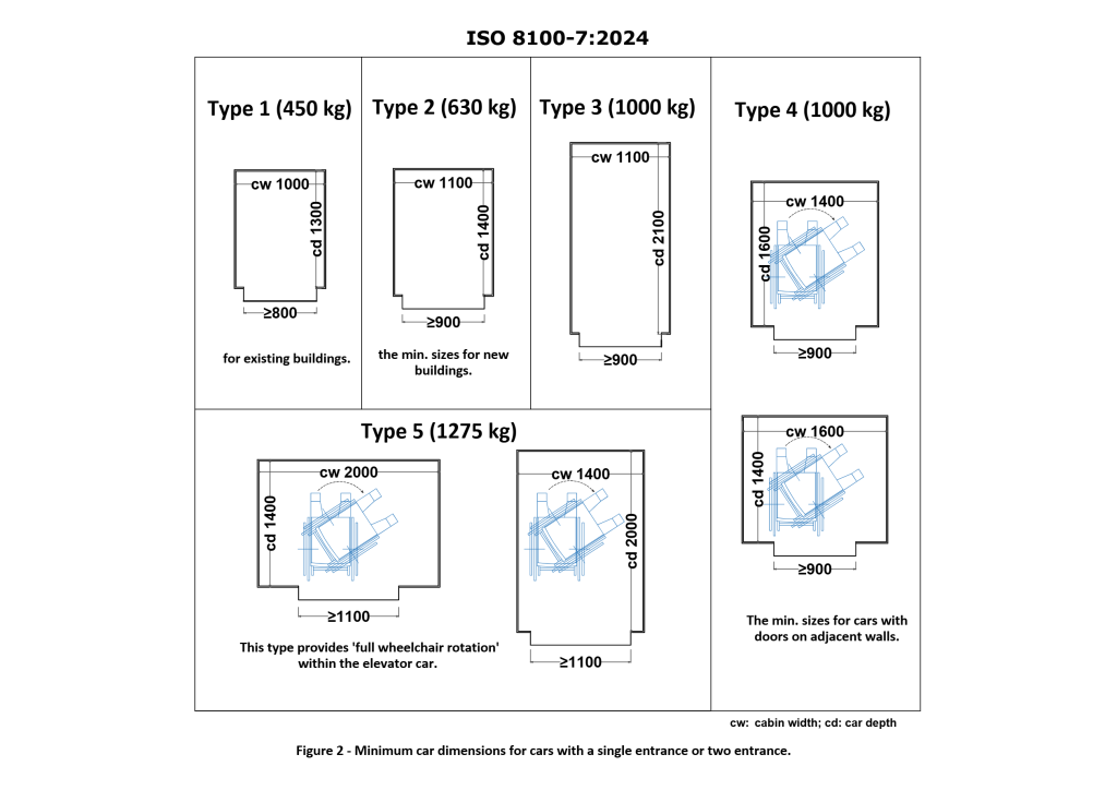
4. Car and Door Dimensions for Accessibility Compliance
To accommodate users with mobility devices, elevator cabins shall adhere to dimension standards based on the intended capacity and door configuration. ISO 8100-7 outlines five cabin types, classified by capacity and layout (single-entry, opposite doors or adjacent doors). Designers must refer to standardized dimensions to ensure compliance, allowing for sufficient turning radius and maneuverability for wheelchairs.
These dimensions directly impact:
- The minimum internal width and depth of the cabin
- The positioning of control panels within ergonomic reach
- The door width and clearance zones
By adhering to these parameters, manufacturers and building developers can ensure that elevators are truly inclusive and in line with both legal obligations and ethical design principles. Both landing and car doors shall be automatic, horizontally sliding and power-operated. Semi-automatic (swing) doors are not acceptable for accessible elevators and are considered noncompliant.
Minimum clear opening (CO) dimensions are:
- For Type 1 cars: Minimum clear opening width = 800 mm (31.5 in.)
- For Types 2, 3 and 4: Minimum = 900 mm (35.4 in.)
- For Type 5: Minimum = 1,100 mm (43.3 in)
In existing buildings (retrofits), Type 2 cars may be accepted with a minimum of 800 mm clear opening.
5. Other Elements That Support Accessibility
5.1. Braille Characters
Braille is not a mandatory requirement for lifts under all international standards. However, when braille is used, it shall comply with ISO 17049, which specifies the format, character spacing and readability for tactile signage.
5.2. Color and Contrast
For users with low vision, strong color and tonal contrast — especially between floors, walls and control panels — is vital for orientation and safety. ISO 8100-7 and ISO 21542 specify luminance contract requirements, promoting matte, non-slip materials and distinct visual cues for improved usability.
5.3. Induction Loop Systems for Hearing Aid Users
If a hearing enhancement system is provided, it shall comply with ISO 4190-5 and be marked with the international symbol for assistive listening devices. This system enables clear communication between hearing aid users and the intercom. It is recommended for public-use elevators, especially in transport and healthcare settings.
5.4. Lighting
Lighting shall provide a minimum luminance of 100 1x in the plane of the item (ISO 8100-7:2024, Table 2), which can be vertical or tilted.
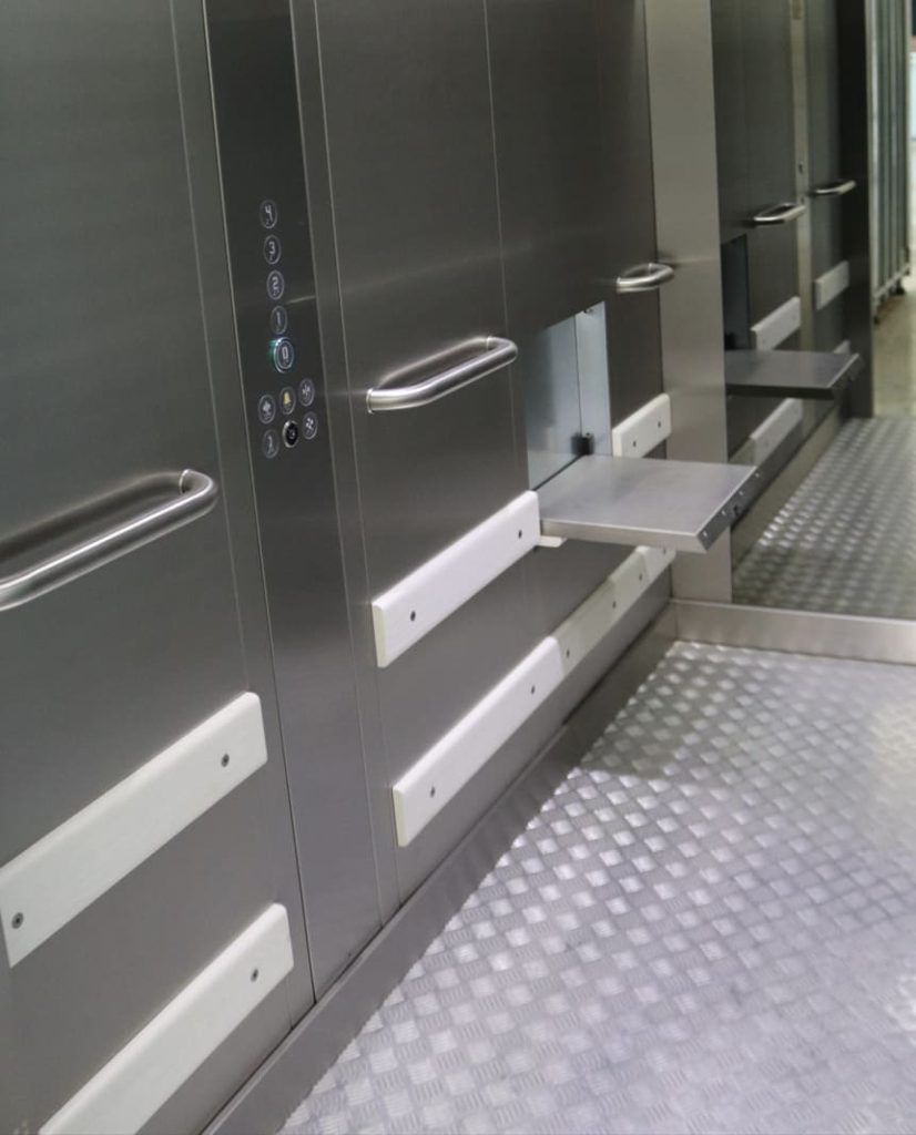
5.5. Tip-Up Seat
Although not mandatory, as per Clase 5.3.2.2 of ISO 8100-7, when a folding seat is provided inside the car, it shall meet the following specifications:
- Seat height from finished floor: 500 mm (19.7 in.) ±25 mm
- Depth: 300-400 mm (11.8-15.7 in.)
- Width: 400-500 mm (15.7-19.7 in.)
- Minimum load capacity: 120 kg (265 lb)
These dimensions ensure safety and usability without compromising floor space for other passengers.
5.6. Landing Call Buttons on Door Jambs
In single-elevator configurations, landing call buttons may be mounted directly on the door jamb, provided the recess in which the button is installed does not exceed 250 mm (9.84 in.) in depth. To ensure adequate maneuvering space and visibility, a minimum clearance of 500 mm (19.7 in.) — preferably 700 mm (27.6 in.) — should be maintained between the button and the nearest adjacent wall.
In cases where two or more elevators are present, landing call buttons must be located between the elevator entrances to serve all cars efficiently. Importantly, the position of the call button (left or right of the door) is not dependent on the door swing or opening direction. Either side is acceptable, so long as clearances and accessibility norms are respected.
6. Enhanced Accessibility Use Cases
In specific public-use environments — such as transit stations, healthcare facilities, retirement homes and other setting where vulnerable users may be present — the application of enhanced accessibility measures goes beyond standard compliance and enters the realm of universal design. Examples of such enhancements include:
- Increasing both door and car interior height to a minimum of 2,100 mm (82.7 in.) for better spatial comfort and easier maneuverability for taller assistive devices
- Clearly marking glass doors or transparent surfaces to reduce confusion and improve visibility for users with low vision
- Installing handrails on all walls that do not contain doors, providing 360˚ support regardless of positioning
- Using matte, non-reflective materials on wall surfaces to eliminate glare and optical interference
- Ensuring that any mirror installed inside the car has a minimum vertical clearance of 300 mm (11.8 in.) from the finished floor level to enhance usability without visual disruption
- Implementing panoramic elevator cabins, where feasible, to reduce the risk of panic during entrapment and allow external visual contact or emergency communication
7. AI Applications for Accessibility in Elevators
AI-based systems, while not mandated under current ISO 8100-7, are in line with Annex D recommendations for increased usability. However, AI-driven systems are rapidly being integrated into modern elevators, especially in technologically advanced countries, with promising results in terms of enhancing accessibility.
Emerging AI applications include:
- Voice command and speech recognition to call the elevator and select the desired floor verbally
- Wheelchair detection systems that can automatically adjust door timing or prioritize car dispatch
- Facial recognition using smart cameras to identify users and personalize the elevator experience based on behavioral patterns
AI-powered elevators can suggest frequent destinations and guide users via location-aware tools, enhancing accessibility and comfort. Yet, without proper safeguards, these systems may pose data privacy risks. Crowd-aware features, already piloted in smart buildings, prioritize accessible rides and are set to become standard.
7. Conclusion: Elevators That Empower
As urban demands grow and technologies evolve, elevator design must shift from mechanical utility to human-centered solutions. Accessibility is not just regulatory; it’s essential engineering for dignity and autonomy. Every detail matters. From tactile surfaces to AI assistance, inclusive elevators enable independent living and civic participation. When lifts respond to diverse human needs, they stop being just machines. They become instruments of social equity. Designers should go beyond compliance. As Directive 2006/42/EC reminds us, good design minimizes stress and maximizes usability — not just for some, but for all.
References
[1] ISO 8100-7:2024 Lifts for the Transport of Persons and Goods Part 7: Accessibility to Lifts for Persons Including Persons with Disability
[2] EN 81-70:2022 Safety Rules for the Construction and Installation of Lifts — Particular Applications for Passenger and Goods Passenger Lifts — Part 70: Accessibility to Lifts for Persons Including Persons With Disability
[3] Lifts Directive 2024/33/EU
[4] European Parliament and Council Directive 2006/42/EC of 17 May 2006 on Machinery, Annex I, Section 1.1. 6 Ergonomics

Get more of Elevator World. Sign up for our free e-newsletter.
![]()


")

![]()