Door Reopening Devices — A Field Perspective
Oct 1, 2020

Light curtains and their blind spots are explained in this Focus on Doors and Sensors article.
by Lakshmanan Raja
The risk that lifts with non-power-operated doors (like swing and manual-sliding doors) will close on a passenger who is boarding and alighting is very slim. However, there is a need for control of such risk with an automatic door system. This necessitates the need for the sensing devices to detect the presence of a passenger at the entrance (or closer) and initiate the reopening. There are code requirements governing this (Table 1). These sensing devices/edges are called “protective devices” under “Automatic Power Operated Doors” in EN 81-20 Clause 5.3.6.2.2.1 (b) and “reopening devices” in ASME A17.1 Rule 2.13.5.
The code is not a design handbook, so it does not specify the type of device to meet its requirements. However, a variety of devices do. The traditional method of providing protection was to use retractable mechanical safety edges. This requires physical contact between the protective edge and the person or object being detected. They are mechanically activated — the protective edges being pushed in the opposite direction to that of door motion causes the switches to open their contacts, which initiates the door controller for stopping, reversing door movement.
Learning Objectives
After reading this article, you should have learned about:
- The code requirements of light curtain and door reopening devices
- The operation of mechanical safety edges and light curtains using horizontal and crisscross beam arrangements
- The resolution of horizontal-beam versus crisscross arrangements
- The challenges of using crisscross beam arrangements and how to overcome them
- How to select the right light curtain model for the correct situation and achieve the required code resolution
Since the operation of retractable mechanical safety edges is mechanical in nature, the devices suffer from wear and tear, so maintenance and periodic inspection and adjustment play a critical role to ensure their proper function. At the same time, to meet the accessibility requirement, single-beam infrared sensors began to be used in addition to the mechanical safety edge. Two pairs of transmitter (Tx) and receiver (Rx) units are installed at the doorway, with the control box usually located at the car top. The infrared (IR) beams are transmitted from the transmitter to the respective receiver. When the beams are interrupted, the door stops and reopens. The main advantage of using such a light beam is its contactless sensing.
As development continued, a multiple IR beam arrangement called a “light curtain” was introduced. This replaced the mechanical safety edge but still provided the protection as required by the code. In the light curtain arrangement, instead of two pointed beams, more IR beams extend from 25 mm above the car sill level to a height of 1,600 mm. This is achieved by having an array of multiple emitters in the Tx unit and detectors at the Rx unit. Each emitter/detector pair operates in sequence to check whether the beam path is intact. It is necessary for only one beam to be blocked for a trigger signal to be sent to the controller to reopen the doors. So, the minimum object size that can be detected is equal to a space between the beams’ center and the size of one beam. The challenge of this type of device, when compared to the mechanical safety edge (which has no blind spot), is that there may be blind spots depending on the spacing between the beams.
Beam Arrangements
The light curtains commonly available in the market use two types of beam arrangements: horizontal and crisscross.
Horizontal
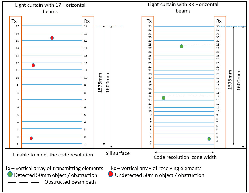
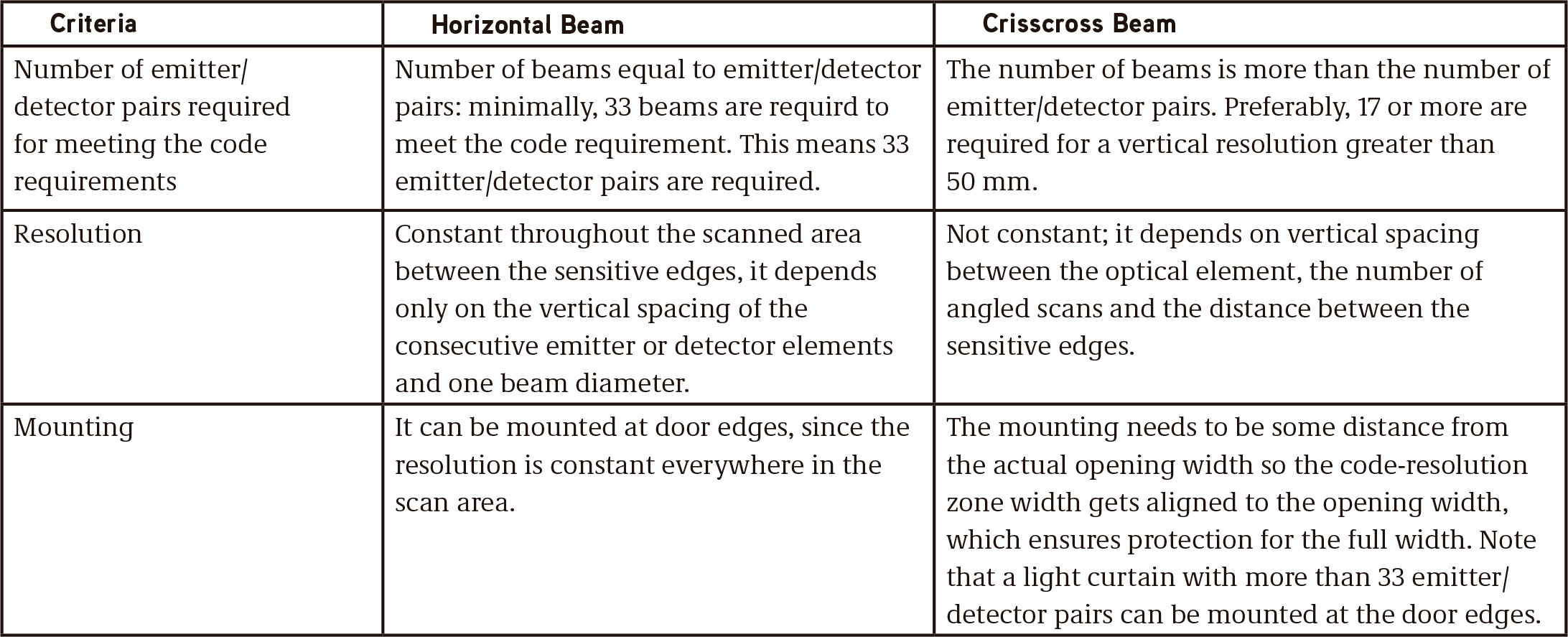
This kind of light curtain uses a simple set of parallel horizontal-beam scanning arrangements. The number of beams is equal to the number of emitter/detector pairs (Figure 1). The scanning area covers the opening distance between at least 25 mm and 1,600 mm above the car door sill. The resolution is 50 mm in diameter, per the code requirement.
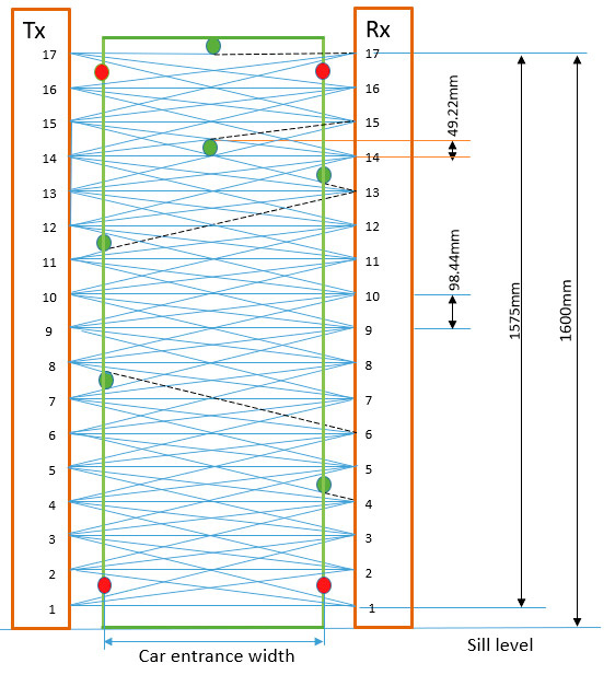
For example, consider a light curtain system with 17 horizontal beams (Figure 1). The bottommost beam is located such that its spacing from the sill plus its beam diameter is less than or equal to 25 mm. This is done to meet the code requirement of starting the protection zone at a vertical distance at least 25 mm from the sill level. The remaining 16 beams will be used for covering the distance of 1,600 mm – 25 mm = 1,575 mm. The spacing between the beam center and its diameter is 1,575 mm/16 = 98.44 mm. This means that an object size smaller than 98.44 mm won’t get detected. Hence, the resolution of this arrangement is 98.44 mm, which does not meet the code-required resolution of 50 mm. To meet this requirement, the following is needed: 1,575 mm/50 mm = 31.5: 32 beams plus one bottommost beam. In total, we require at least 33 emitter/detector pairs for horizontal beam arrangements.
It is important to note in Figure 1 that the resolution of such a horizontal beam arrangement is constant throughout the area of coverage, except for the area between the sill and first beam, where it is at least 25 mm.
Crisscross
As the resolution of the light curtain depends on the beam spacing and beam diameter, each detector in a crisscross beam arrangement is programmed to scan multiple emitters. Thus, the number of beams is increased, which results in reduction in the space between each. If each detector scans three emitters, the arrangement is called “three-way,” and if each detector scans five emitters, it is called “five-way” (Figures 2b and 2c, respectively). In a three-way-scan arrangement, each detector will make one horizontal scan, one angled-down scan and one angled-up scan. A five-way arrangement will have one horizontal, two angled-up and two angled-down scans.
The scan arrangements are programmed in the sensor control algorithm and constrained by capability of the detector/emitter optics. From Figures 1 and 2a, we know that a light curtain with 17 emitter/detector pairs using horizontal beams is unable to meet the code requirements. But, using the same 17 emitter/detector pairs in a crisscross arrangement and by adding one angled-up and angled-down scan (Figure 2b), we are able to meet code-required resolution at certain areas (shown in green). A five-way-scan arrangement increases this area further (Figure 2c). To summarize:
- Figure 2a shows 17 emitter/detector pairs using a horizontal scan arrangement, which is unable to meet the code-required resolution.
- Figure 2b shows 17 emitter/detector pairs using three-way crisscross arrangements in which 15 detectors scan three emitters each. The topmost and bottommost detectors scan two emitters each. Total beams: 49
- Figure 2c shows 17 emitter/detector pairs using five-way crisscross arrangements in which 13 detectors scan five emitters each. Rx16 and Rx2 scan only four emitters each. Rx17 and Rx1 scan only three emitters each. Total beams: 79 Figure 2 showed that, unlike the horizontal scan, the crisscross scan arrangement can meet the code resolution with fewer optical elements. However, there are some challenges: the resolution is not constant throughout the coverage area, and poor resolutions are seen near the sensor edges and between the sensor edges (zones 1 and 2, respectively, in Figure 2).
Overall resolution depends on such factors as:
- Vertical spacing between consecutive emitters or detectors
- Number of beams scanned by each detector
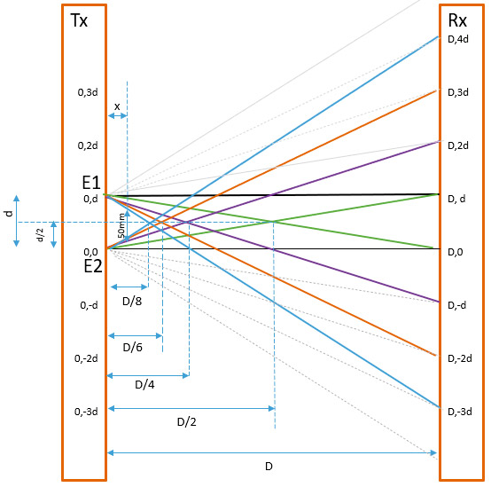
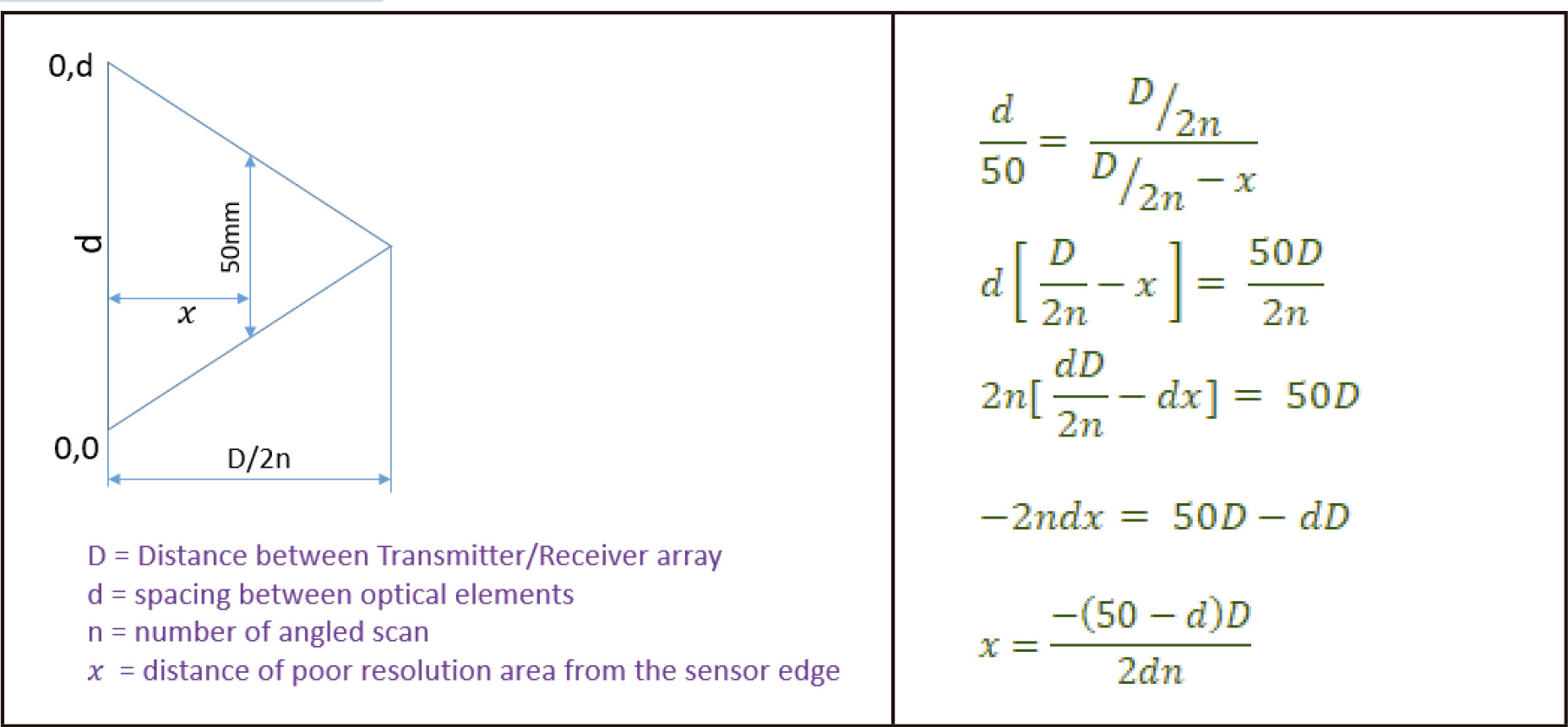
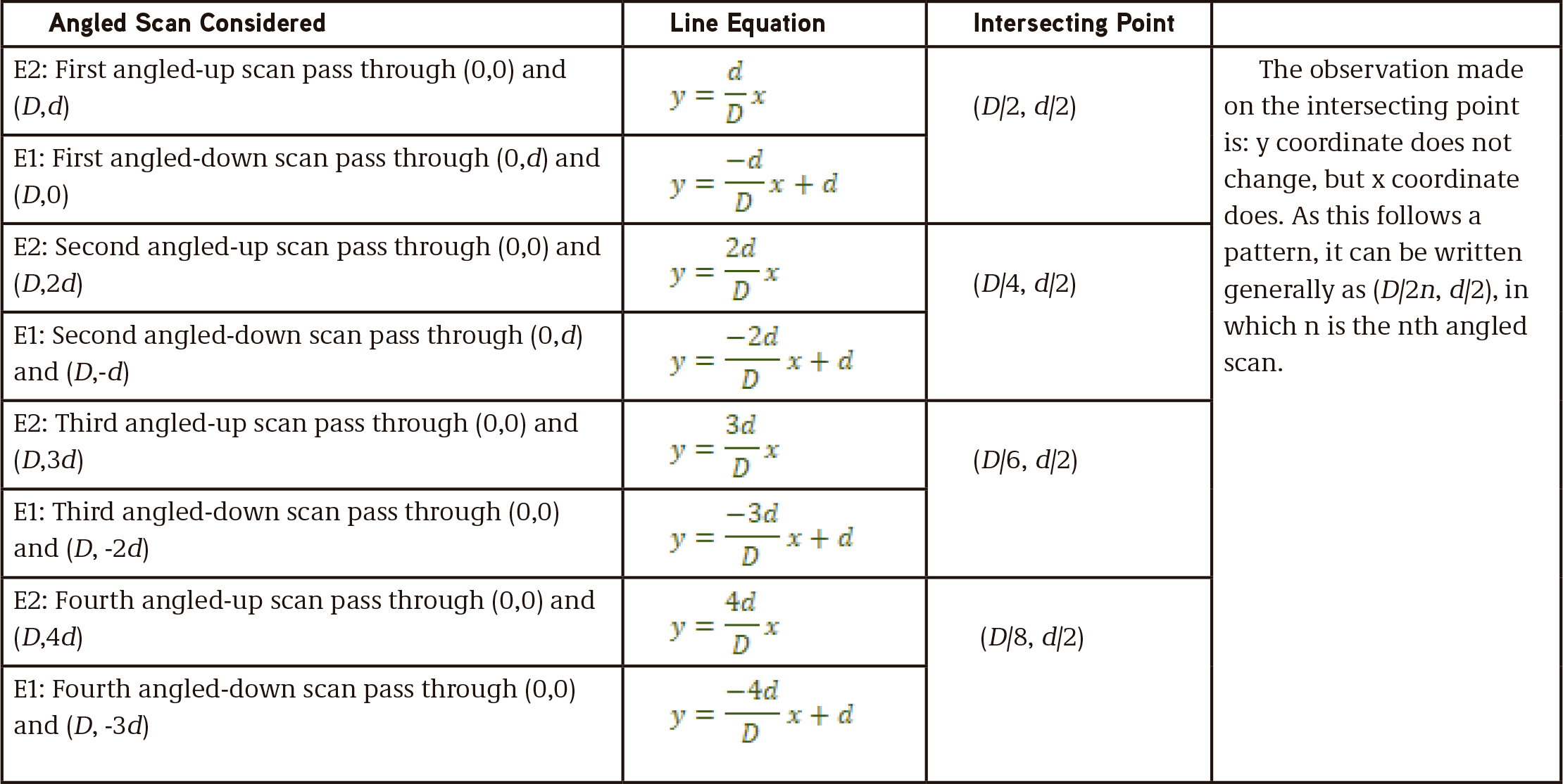
- Horizontal distance between the Tx/Rx edge (array). Considering the poor resolution at zone 1, which is closer to the sensor edges, the intersecting position of the beam decides its width from the surface of the sensor edge. Only the angled scan beams intersect each other. The intersecting point can be found (referencing Figure 3) with the four angled-down scans for emitter E1 and four angled-up scans for emitter E2. The emitter/detector position was mapped to x and y axes with position E2 as the origin. The angled-down scan from E1 will intersect with the angled-up scan from E2. We obtain the intersecting points from the straight-line equation for each beam (Table 2).
The resolution is 0 mm at the intersecting point. However, the code allows resolution of up to 50 mm. So, what needs to be found is the distance from the sensor surface at which the resolution of 50 mm is obtained. Using the similar triangle concept and considering the triangle formed by the signal to emitter E1, E2 and the intersecting point as shown in Figure 4, the distance x, width of poor-resolution area from the sensor edge, can be calculated.
From the calculation in Figure 4, the distance x, width of the poor-resolution area near the edge of the sensor surface, is given as:
From Eq. (1), the width x of the poor-resolution area near the sensor edges will be:
- Zero if the vertical spacing between the consecutive emitter/detector element (d) is 50 mm.
- Directly proportional to the distance between the sensor edges (D)
- Inversely proportional to the number of angled-up or -down scans (n)
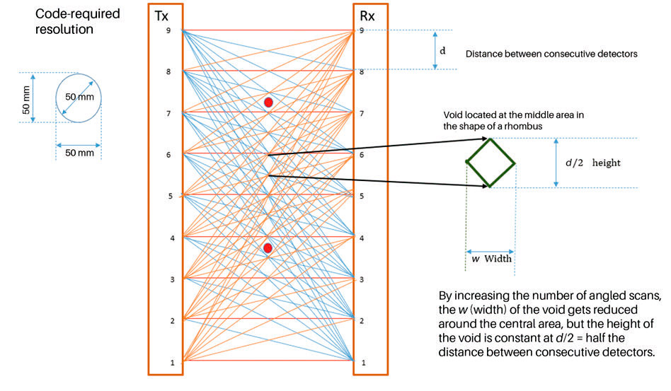
Consider the poor resolution at zone 2, which is midway between sensor edges and in the shape of a rhombus (Figure 5). By increasing the number of angled scans, the rhombus width is reduced at the central area. However, the height of the rhombus is maintained constant, irrespective of the number of angled scans, which is equal to half the distance of the spacing between detectors (d).
For the light curtain with 17 pairs of optical elements, d = 98.44 mm, so the height of the rhombus is 49.22 mm. If the light curtain uses 16 pairs of optical elements, the worst vertical resolution nearer to the sensor surface is d = 105 mm, and the height of the void is 52.5 mm, which does not meet the resolution requirement of the code. So, most light curtain manufacturers prefer to use more than 16 emitter/detector pairs for crisscross arrangement.
How Resolution Is Affected by Number of Angled Scans
It can be derived from Eq. (1) that the poor-resolution zone width is inversely proportional to the number of angled scan n:
For a fixed installation of sensitive edges, where the Tx and Rx are installed at the entrance slam post of the lift car, the distance D between them will be constant. If the spacing between the consecutive emitter or detector is maintained constant, the resolution of such an arrangement depends on the number of angled scans. This can be seen from Figure 2b and 2c.
For the light curtain with 17 emitter/detector pairs with five-way-scan arrangements, each detector scans for five emitters. For example, the detector Rx3 will be scanning Tx1, Tx2, Tx3, Tx4 and Tx5 emitters. Figure 6 shows that, by increasing the angled-up and -down scanning, the protected area width (enclosed in green) is increased, and the blind-spot area size nearer the sensor surface area is reduced. The sensitive edges need to be fixed at a distance away from the car opening edge to align the car opening width to the code-resolution zone width. This enables the car opening width to be fully protected with the required resolution. However, this presents other concerns: as the number of angled scans increases above one, the detectors at the top/bottom end of the array become unable to perform a full five-emitter scan. The detectors Rx16 and Rx2 scan only four emitters, so the resolutions at the area between Rx16 and Rx17, and Rx1 and Rx2 are compromised. However, this can be balanced by adding another angled-down scan to Rx17 and another angled-up scan to Rx1. Still, this all depends on the sensor control algorithm.
How the Resolution Is Affected by the Distance Between the Tx and Rx Array
When the distance between the Tx and Rx varies (i.e., if at least one light curtain sensitive edge is mounted on the moving door panel), the width of the code-compliant zone also varies in a constant ratio. It can be seen from Eq. (2) and is shown in Figure 7.
However, when Tx and Rx get closer, the detector’s ability to do angled-up and -down scans will be reduced. Eventually, only the horizontal beam exists between two edges. At that time, the resolution is equal to vertical spacing between the optical elements. However, the above depends on the optical design of the emitter and detector, their lenses, and the beam spread. Note that, per EN 81-20, protective devices may be rendered inoperative in the last 20 mm of the door-closing gap.
Self-Diagnostic and Failure Mode
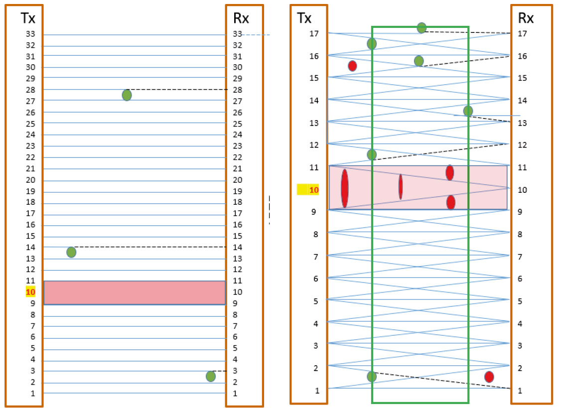
Apart from resolution, other factors, like self-checking (diagnostics), are important, especially when the number of emitter/detector pairs is lower, to meet the code resolution. Consider the horizontal beam arrangements with 33 emitter/detector pairs: beam spacing is 49.2 mm. One emitter or detector failure going undetected, and the light curtain being allowed to function, results in a blind spot of 2 X 49.2 = 98.43 mm around that failure area (Figure 8). Most of the crisscross arrangements achieve the code resolution with fewer emitter/detector pairs but with more beams. So, one emitter failure will remove all its respective beams from the protection area, and the blind spot will be critically large (Figure 8). Such a situation should trigger the failsafe operation of allowing the door to close with reduced kinetic energy and with an acoustic signal per the code requirement.
Learning-Reinforcement Questions
Use the below learning-reinforcement questions to study for the Continuing Education Assessment Exam available online at www.elevatorbooks.com or on p. 118 of this issue.
- What are the advantages of a light curtain with a horizontal beam arrangement?
- What are the challenges and benefits of using a crisscross beam arrangement in a light curtain?
- Which type of light curtain arrangement is preferred for an elevator with a side-opening door where there is no recess behind the slam post at the door closing end?Why?
- Why is the self-check function of a light curtain important?
- While doing repair work, the technician plans to replace a defective light curtain with newer one. Which factors need to be considered?
Conclusion
The public has been used to doors with a mechanical edge for a long time, and many passengers have a habit of keeping the doors open by pressing on the mechanical edges (although this is an unsafe behavior). Some riders will continue to do this, despite mechanical edges being progressively replaced with light curtains. If the hands, for example, are placed in a light curtain’s blind spot, the door will not be kept open. Hence, understanding the blind spot of a light curtain at the edges is important for lift professionals.
Horizontal beam arrangements provide a constant resolution throughout the area protected by the beams. The protected area depends solely on the vertical spacing between the consecutive emitter or detector. However, if a crisscross beam method is used instead, the resolution depends on more variables: the vertical spacing between the consecutive emitter or detector, the scan pattern used and the horizontal distance between the Tx and Rx arrays.
The following key points have been observed in this article. Your author thinks they might serve as a rule of thumb for light curtain selection:
- A light curtain with more than 33 emitter/detector pairs, irrespective of beam arrangement and fixing location, will meet the code-required resolution.
- A light curtain with fewer than 33 emitter/detector pairs must use a crisscross arrangement to meet the required resolution. It should be fixed some distance from the opening it is protecting.
- A light curtain with fewer than 17 emitter/detector pairs may not be able to meet code-required resolution and should be avoided.
Elevator professionals modernizing or replacing door protective devices should take note of these points so the installation complies with code requirements on detecting obstructions.


Get more of Elevator World. Sign up for our free e-newsletter.


