Joseph C. Tamsitt’s Second NAEC Education Program 1960-1964: Lessons
Aug 1, 2025

This History article looks at the specifics of the program and its success.
by Dr. Lee Gray, EW Correspondent
The March 1960 issue of ELEVATOR WORLD included the announcement of the second National Association of Elevator Contractors (NAEC) education program led by Joseph C. “Joe” Tamsitt (1901-1984). The first program followed a correspondence course model and engaged more than 2,200 participants.[1] The new program was developed in partnership with EW, with the magazine serving as the interface with program participants. Between March 1960 and May 1964, Tamsitt published 30 lessons designed to “attempt to show the reader how to use a diagram; to follow any circuit; to analyze a symptom; and to locate and correct a fault … After a thorough understanding of diagram reading has been realized, typical (and actual) faults will be discussed and traced.”[1] He noted that the program: “will not be easy for either of us. You must be patient with constant repetition. Many of you will find the first group of articles dull indeed, for you will be more advanced than average in your knowledge. Stick with us. It will become more complex as we progress.”[1] In addition to the regular lessons, Tamsitt also reported that:
“To liven what might become a deadly ordeal, we plan to intersperse with the lessons, articles on components such as timers, rectifiers, generators and A.C. and D.C. motors.”[1] This month’s History article will address the content of the program’s lessons; a future article will address what became known as the “Bonus Articles.”
The 30 lessons were divided into five groups. The four primary groups focused on the analysis of a specific wiring diagram; the fifth group was composed of four articles. The format of the first 16 lessons included a series of questions that followed the text. Answers were published for questions associated with the first seven lessons. In March 1961, program participants were informed that answers would no longer be provided:
“We believe it would be more of an incentive for the Educational Program students to apply themselves if the answers to Lesson Questions did not come too easily. For that reason, we are not going to publish answers for a number of future lessons. If a question stumps you, drop a postcard to Mr. Joe Tamsitt, c/o Keystone Controls, 1220 S. Ridgely Street, Baltimore, Md., and he will try to clear it up for you. The questions will become more difficult as the Program progresses, and we would like to judge from the reaction on the postcards whether or not they are too difficult.”[2]
Lessons 17 to 30 did not include questions; readers were instead encouraged to send questions directly to Tamsitt.
As a critical preface to engaging the lessons, Tamsitt provided a chart of electrical symbols:
“To begin with – Here are a number of straight diagram symbols which ought to be placed in the front of your notebooks and memorized. The electrical symbols used in our drawings are somewhat similar to those in use throughout the industry. However, there are some which are peculiar to Otis and other manufacturers, and we will publish these in future issues for your reference.” [3]
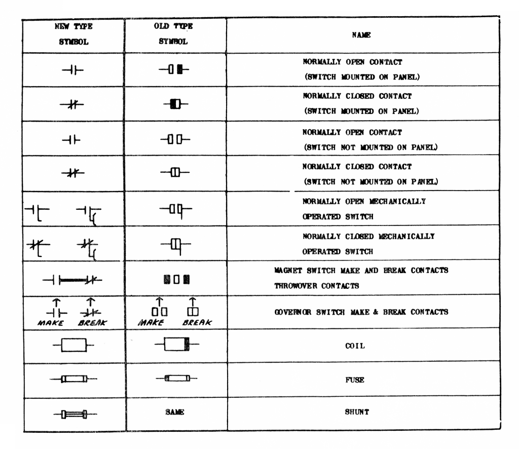
Two pages of “symbols used generally” were provided, which were identified as “AIEE Standard” and “Keystone Standard” symbols (Tamsitt was employed by Keystone Controls) (Figure 1). Six pages of “straight diagram symbols as used by the Otis Elevator Co.” were published between April and June 1960 (Figure 2). Tamsitt noted that:
“The electrical symbols used in our drawings are somewhat similar to those in general use throughout the industry. However, there are many that are peculiar to Otis which do not follow the standard pattern. The Otis symbols have had numerous revisions in the past due to changes in the application of the symbol and also to the change in the design of the part represented. These tables show some of the old and new type symbols, with the functional name of each.”[4]
While the history of wiring diagram symbols and nomenclature is beyond the scope of this investigation, it is of interest that Keystone and Otis employed unique, non-standard symbols. Their presence suggests the need for the vertical-transportation (VT) industry to develop nomenclature in “real time” as innovations occurred, rather than wait on professional organizations to “catch up.” The publication of these charts in association with the education program also appears to imply that VT system wiring diagrams were readily available to technicians either on-site or through other means.
Lessons one through six concerned the analysis of a basic VT control circuit, with the drawing published as Print No. C-0303- AA (Figure 3). Tamsitt introduced the first lesson — and the program — by stating: “With this lesson you will start using the symbols and also learn how to piece a circuit into a diagram.”[5] In fact, a primary focus of the first three lessons was understanding the operation of the various safety features found in the control circuit. A representative example in Lesson One is as follows:
“Following the circuit downward from L1, L2 and L3, we see that L1 and L3 lines are connected to TOR. This is a thermal overload relay. This device overheats if the motor is required to do too much work, and when it overheats a temperature operated contact will cause the power to be removed from the motor, protecting the motor from damage.”[5]
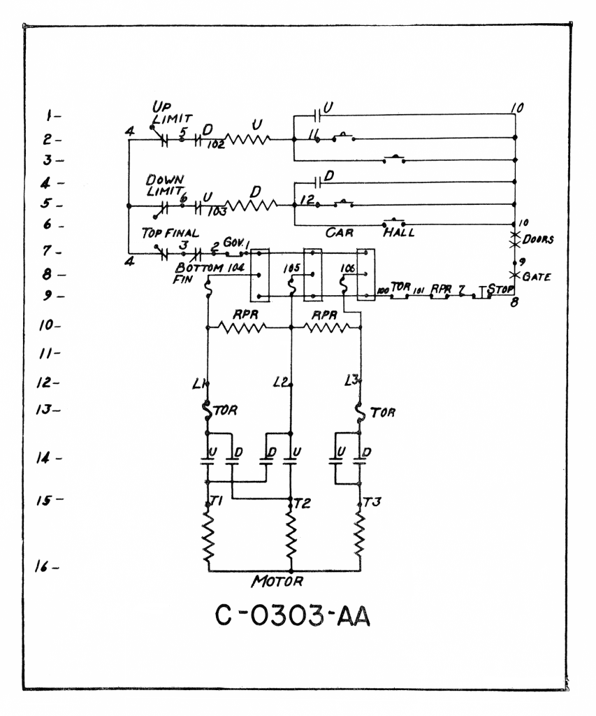
Beginning with lesson four, Tamsitt explored how to “run through the operation of this small and simple control, and look for various troubles that might occur.”[6] The “trouble” scenarios presented by Tamsitt included: 1.) “Suppose the car overtravels in the up direction? … This will cut off all power to the entire operating circuit, and the car cannot move.” 2.) “Let us now assume the car is at the top floor in a normal position and will not run down. How do we find the trouble?” and 3.) “We will now attempt to find trouble in this job with a test lamp. The car is still at the top floor, and must run down.”[7,8]
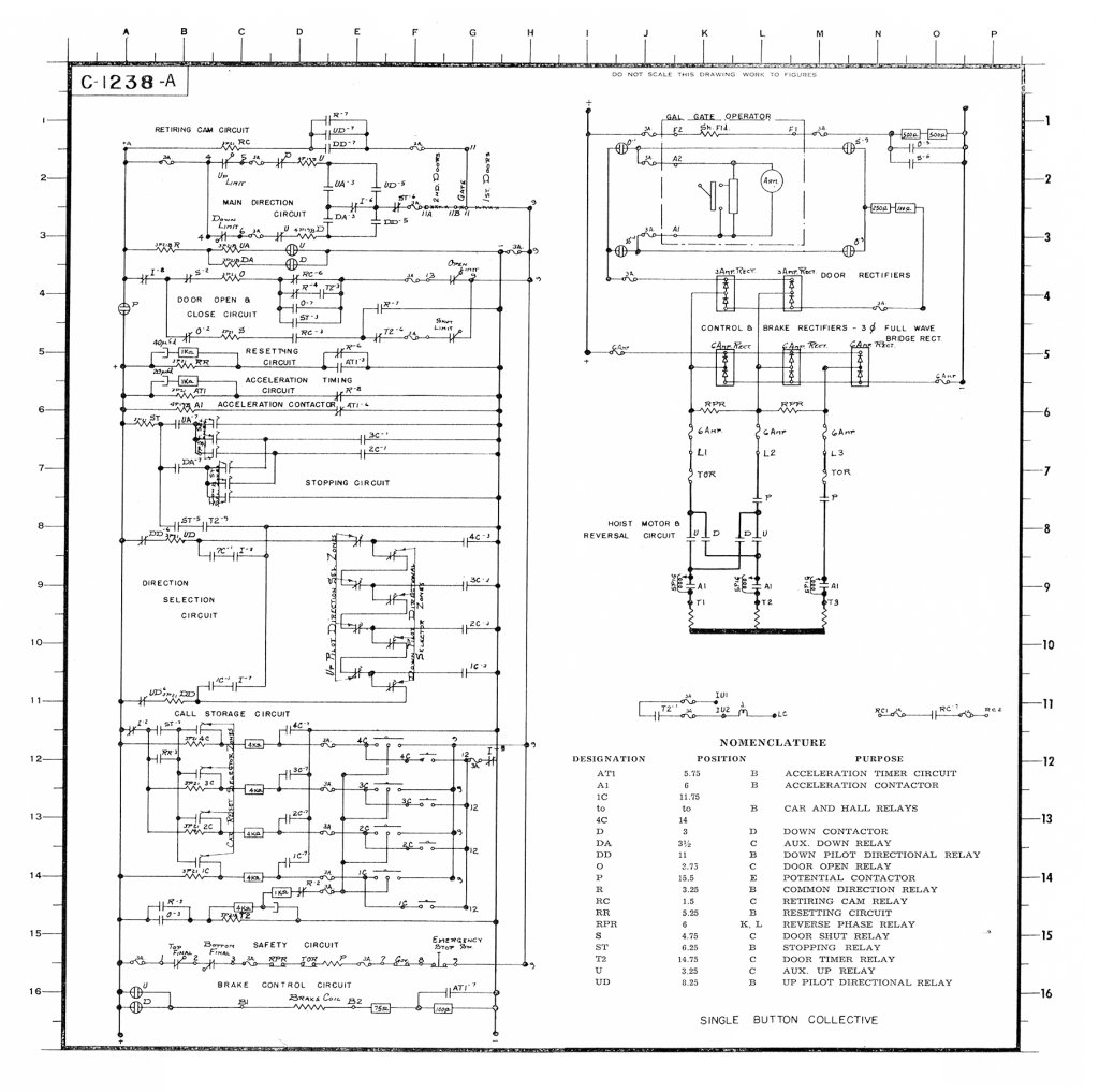
The next wiring diagram, Print No. C-1238-A, was published in two parts, with students expected to remove the pages from the magazine and “assemble” the complete drawing (Figure 4). According to Tamsitt: “This print was selected because it is a single button collective, which will start us into the “stored call” method of control, and also because it has a retiring cam with a car door operator. It (also) has a single speed AC Motor with one step of acceleration.”[9] The lessons focused on 1.) picking up relay calls and determining the car’s detection of travel; 2.) closing the car door, lifting the retiring cam, releasing the brake and running the car; 3.) stopping the car, opening the door, canceling the call, closing the door and starting the car; and 4.) canceling the calls as they were answered.[10,11,12]
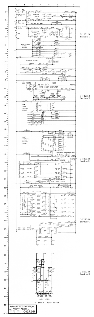
The next drawing, Print No. C-1272-B, which presented a two-speed AC system with collective-selective control, was used in seven lessons. The production of this drawing differed in that its format was a direct response to student complaints:
“Due to the fact that we have had some criticism of the small size of the reproductions, we are presenting this one in a new form. The two supply lines are on the outside, as usual, but instead of the diagram being a conventional rectangle, it will be long and narrow. As it will consume some six pages, it will be in several issues. They will be so arranged that, when removed … they may be attached to each other to form a full-size diagram.”[13]
The drawing was divided into six sections, with one page devoted to system nomenclature. The individual drawings were 7.5 in. by 9.5 in. in size, with the assembled drawing measuring 37.5 in. by 9.5 in. (Figure 5).
The first lesson addressed safety circuits (including interlocks, limits, stop switches and governor contacts), up and down direction contactors and the brake and auxiliary brake relays.[13] The following four lessons addressed “the setting up of car and hall calls, and their cancellation,” “slowing down, stopping and leveling of the car,” “direction selection, car call resets, and hall call resets” and “door operation, brake operation and the safety circuits.” [14,15,16,17]
In the final two lessons, Tamsitt informed his students that “we will attempt to do the thing for which these lessons are supposed to be preparing you — find the trouble when a car will not operate.”[18] The first scenario was simultaneously specific and vague: “Assume that the car is at the third floor, the doors are open and will not close. We will check all possible conditions of fault.”[18] The second scenario was, perhaps, overly specific:
“The maintenance man reports that if the car is at one, he can press #4 button or #3 button and the car will run up. If he presses #2 only, it will not move. If either #3 or #4 is then pressed, the car will run. If the car is at the top, it will run down for #2 or #1 button. #3 only will have no effect. Without any equipment, we can find this trouble.”[19]
Given the complexity of the second problem, Tamsitt reminded his students that: “Shooting trouble is very easy, if logic is the main tool that you use.”
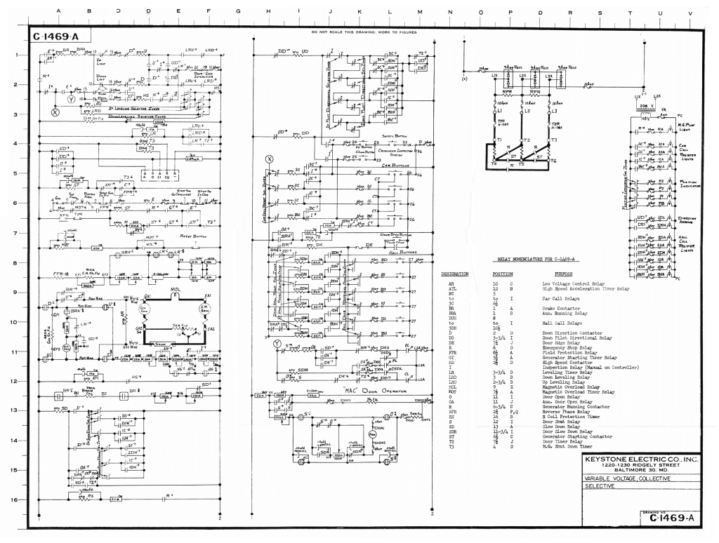
The final drawing employed in the education program, Print No. C-1469-A, was a diagram of a variable voltage collective-selective system “with a door operator, automatic MG shutdown and Wye start — Delta run on the MG drive motor.” This drawing was the subject of nine lessons and was also the largest drawing produced for the program. It was included as a fold-out in the November 1962 issue of EW and measured 24 in. by 18 in. (Figure 6). The first four lessons explored how to start the motor generator, get the car up to high speed, slow it down in a normal manner and level it at the landing.[21,22,23,24] The remaining lessons primarily focused on various troubleshooting scenarios, including one that summarized the program’s goals:
“This one will be on the car not leaving the floor. As you know, we could go on indefinitely shooting trouble on a complex system. Our purpose will be served, however, when our students can recognize the possible sources of trouble and analyze the definite source from observation, tests and elimination by using a meter. When they can do this, they can, if given time and a print, fix any elevator of any make or control system. Study and practice will shorten the time required. Study and practice will make the tests quicker, easier and more positive. In other words, teaching the ways to do this is the whole purpose of the course. Here we are with a car that will not run. Here is where it does not pay to ‘just poke’ at the switches.”[25]
Tamsitt’s emphasis on logical, systematic and practical problem-solving strategies as an effective approach to maintaining VT systems permeated all 30 of the program’s lessons.
In addition to the 26 lessons focused on the four wiring diagrams, Tamsitt wrote four articles that were also presented as “lessons.” The first article (published in two parts) concerned “the theory of operation, the inherent advantages and disadvantages, and the trouble to be anticipated in” DC and AC relays.[26,27] The second article, “Dissecting a Vacuum Tube,” offered an introduction to what were relatively new VT system components:
“You will note that the title narrows the very broad subject of Electronic Tubes to one specific tube. Reproduced as Figure 1 you will see a page reproduced from a book called Essential Characteristics of Receiving Tubes. It is published by G.E., costs US$1.00 and is available (or a comparable book is available) at any major radio supply house. You will find such a book a necessity in any electronic work. If you do not know what the tube is supposed to do, you will not know whether it is operating correctly, or where the difficulty may lie … If there is sufficient demand a series of tube applications could be worked up. This, of course, would be quite lengthy, as the basic types of tubes are thermionic, or heat operated, such as the one discussed, gas filled tubes, light sensitive tubes, cold cathode tubes and several other generic types. Each of these divisions have many variations.”[28]
Students who rushed out to buy the recommended book might have been somewhat overwhelmed to learn that the book was 260 pages long and covered receiving tubes, picture tubes and special-purpose tubes. The slightly whimsical title (and introduction) to his third article, “In the Good Old Summertime,” addressed the broad topic of year-long or seasonal VT maintenance:
“When you were young enough to fish with a cork and a bent pin, you looked forward to the summertime as a time of pleasant heat, the swimming hole and fishing off the bridge while cooling your bare tootsies in the stream beneath. Now you are older (perhaps not much wiser) and concerned with keeping an assorted lot of mechanical and electrical monsters operating as well in August as they did in December. Why shouldn’t the operation be identical? … How might these prickly heat troubles be overcome?”[29]
His final article-based lesson, “Why A.C. Motors Fail,” was more pragmatic:
“You are aware, no doubt, of many of the reasons that alternating current motors fail, but there may be some reasons new to you. In any event, a review will do no harm, and perhaps will be of some benefit.”[30]
In a world filled with online educational opportunities — offered as either synchronous or asynchronous courses — it may be challenging to imagine pursuing a program that appeared in print, with direct communication with the teacher primarily dependent on the speed of the U.S. Postal Service (which, admittedly, was likely faster in the 1960s). However, given Tamsitt’s conversational writing style, and his responsiveness to student inquiries, his program bears a remarkable resemblance to contemporary asynchronous online courses. The nature of the connection between Tamsitt and his students was indicated in October 1962 when he reported:
“We like your questions. They indicate the direction we should aim our efforts. We hope to continue the service whereby we try to help the field man solve problems. To date, some 2,964 inquiries have been answered. An increasing number come by telephone from people who want an answer now, and although this does not give us much time for consultation with experts, we do the best we can.”[31]
At this point, the program had been in existence for approximately 30 months, which yields an average rate of 100 inquires per month. While this may not rival modern email traffic, the volume is remarkable and reflects the students’ and teacher’s active engagement with the program. A future article will examine the supplementary or “Bonus Articles” that constituted a critical aspect of this important early educational program.’
References
[1] Joseph C. Tamsitt, “Program Introductory Letter,” ELEVATOR WORLD (March 1960).
[2] NAEC Education Program Note, EW (March 1966).
[3] Joseph C. Tamsitt, “Symbols Used Generally,” EW (March 1960).
[4] “Straight Diagram Symbols as Used by the Otis Elevator Co.,” EW (April 1960).
[5] Joseph C. Tamsitt, “Lesson I: Using Print No. C-0303-AA, EW (March 1960).
[6] Joseph C. Tamsitt, “Lesson IV: Using Print No. C-0303-AA, EW (June 1960).
[7] Joseph C. Tamsitt, “Lesson V: Using Print No. C-0303-AA, EW (July 1960).
[8] Joseph C. Tamsitt, “Lesson VI: Using Print No. C-0303-AA, EW (September 1960).
[9] Joseph C. Tamsitt, “Lesson VIII: Using Print No. C-1238-A,” EW (February 1961).
[10] Joseph C. Tamsitt, “Lesson IX: Using Print No. C-1238-A,” EW (March 1961).
[11] Joseph C. Tamsitt, “Lesson X: Using Print No. C-1238-A,” EW (April 1961).
[12] Joseph C. Tamsitt, “Lesson XI: Using Print No. C-1238-A,” EW (May 1961).
[13] Joseph C. Tamsitt, “Lesson XII: Using Print No. C-1272-B,” EW (April 1961).
[14] Joseph C. Tamsitt, “Lesson XIII: Using Print No. C-1272-B,” EW (August 1961).
[15] Joseph C. Tamsitt, “Lesson XIV: Using Print No. C-1272-B,” EW (October 1961).
[16] Joseph C. Tamsitt, “Lesson XV: Using Print No. C-1272-B,” EW (November 1961).
[17] Joseph C. Tamsitt, “Lesson XVI: Using Print No. C-1272-B,” EW (November 1961).
[18] Joseph C. Tamsitt, “Lesson XVII: Using Print No. C-1272-B,” EW (February 1962).
[19] Joseph C. Tamsitt, “Lesson XX: Using Print No. C-1272-B,” EW (September 1962).
[20] Joseph C. Tamsitt, “Lesson XXI: Using Print No. C-1469-A,” EW (November 1962).
[21] Joseph C. Tamsitt, “Lesson XXI: Using Print No. C-1469-A,” EW (November 1962).
[22] Joseph C. Tamsitt, “Lesson XXII: Using Print No. C-1469-A,” EW (December 1962).
[23] Joseph C. Tamsitt, “Lesson XXIII: Using Print No. C-1469-A,” EW (January 1963).
[24] Joseph C. Tamsitt, “Lesson XXIV: Using Print No. C-1469-A,” EW (February 1963).
[25] Joseph C. Tamsitt, “Lesson XXVII: Using Print No. C-1469-A,” EW (August 1963).
[26] Joseph C. Tamsitt, “Lesson VII: The Theory of the Relay, Part one,” EW (December 1960).
[27] Joseph C. Tamsitt, “Lesson VII: The Theory of the Relay, Part two,” EW (January 1961).
[28] Joseph C. Tamsitt, “Lesson XVIII: Dissecting a Vacuum Tube,” EW (April 1962).
[29] Joseph C. Tamsitt, “Lesson XIX: In the Good Old Summertime,” EW (June 1962).
[30] Joseph C. Tamsitt, “Lesson XXVIII: Why A.C. Motors Fail,” EW (November 1963).
[31] Joseph C. Tamsitt, “Plans for the Coming Season,” EW (October 1962).

Get more of Elevator World. Sign up for our free e-newsletter.
![]()


![]()