Methodologies for Designing and Developing New Concepts in Vertical Transportation
Dec 1, 2012

Escalator design, models and methodologies are a few of the key points in this article.
by Juan David Cano-Moreno, José María Cabanellas Becerra, Jesús Félez Mindán and Carlos Labajo Tirado
Escalators and moving walks are multibody systems with a basic design more than a century old. Developed methodology allows studying and improving any subsystem of both systems. In addition, new concepts can be developed and tested without the necessity and cost of real construction. CITEF (Spanish Railway Technologies Research Center) has been modeling escalators for more than four years. Several complex and innovative models have been developed to characterize static, kinematic and dynamic escalator behavior. Escalators’ many mechanical elements complicate the modeling task. However, methodologies and tools have been developed in order to automate it, saving computational and time costs. Developed methodologies have been validated by comparing real measurements and simulated outputs from a dynamic model.
Introduction
The modern escalator design comes from inventions more than 100 years old. The first patent was awarded to Nathan Ames in 1859 for a revolving stairway in the form of an equilateral triangle (Figure 1).[3] Subsequent patents of lifting mechanisms converged rapidly to the design. Inventors like G.A. Wheeler, J.M. Dodge and Charles Seeberger have several escalator patents.[5] The 1900 World’s Fair in Paris displayed four different kinds of escalators, including J. Reno’s (Figure 2).
Until now, basic mechanical design had not changed. Therefore, escalators became a commodity. Recent patents, however, show new lines to follow, and accessibility and safety are present in some patents regarding mobile skirt.[7] Mobile skirt has been designed to avoid entrapments between fixed and mobile parts of escalators. Other patents try to minimize velocity polygonization in turnovers and transition zones. Anti-polygonization devices increase the lifecycle of chain components and decrease vibration and noise levels.
On the other hand, escalator behavior simulation is an unexplored field. Only a few models can be found in the technical bibliography.[1-3 & 8] CITEF is focusing its efforts on simulation models in order to reduce experimental costs and accelerate innovation and improvement processes.
Basic Escalator Design
Escalators include a chain of steps that travel in a loop to provide a continuous movement along a specified path. The steps are connected to two continuous loops of roller-chain links (one per side), including a plurality of rollers that interact with a drive mechanism. Conventional systems are gear driven. As roller-chain links move, the steps move as desired. Each step is connected to two rollers on each lateral part of the step (inner and outer rollers). Only the outer rollers belong to the roller chain (Figure 4). Both are guided by two different guides. The chain is tensioned in the lower zone using sliding guides and two preloaded springs that work in the horizontal direction.
The gear-drive system in the upper zone is the conventional traction system, though there are some patents on linear-traction systems that operate in right zones. Outer rollers engage into two gear wheels (Figure 5).
Escalator Simulation Models
Escalator improvements have demonstrated their validity only experimentally. This supposes a high cost of resources and time, thus causing a bottleneck for its evolution. In order to accelerate this process, static, kinematic and dynamic models have been developed. All models are part of a full methodology partially described in previous papers.[3]
Static Models
Some models have been programmed in Matrix Laboratory (MATLAB) software to obtain an idea about where the maximum force values are and how their distribution is along the time and guide. Also, these models have kinematic outputs. For instance, chain-link pitch influence has been studied for three different lengths: 0.405 mm, 0.225 mm and 0.165 mm (Figure 6). Roller-guide reaction force and chain-link longitudinal forces are represented for the lower turnover. The results show that as chain-link pitch decrease, chain-link longitudinal force tends to be constant, and reaction force value decreases.
This program can simulate any geometry; therefore, parameterized turnover or full guides can be introduced in order to obtain robust designs. A turnaround, defined as two circular zones joined with a tangent straight line, has been studied, varying two radii and the angle between the straight line and horizontal zone (Figure 7).
Factorial design and statistical treatments have been used for obtaining some conclusions about this design. Clustering and multivariate linear regression techniques have been used. Figure 8 shows some turnover geometries and corresponding outputs.
Kinematic Models
Most kinematic models have also been simulated in static and dynamic models. These models have been used as a viability filter for new designs. Interference analysis is an important and basic phase in new concept developments. CITEF has developed models with two main objectives:
- Analysis of existing designs
- Development of new concepts in escalators
These models have been designed and simulated with CATIA software. Kinematic behavior only needs simplified models. Figure 9 shows a model of a conventional escalator represented with three steps, two guides, and its rollers and chain links. This kind of model allows users to obtain all main kinematic outputs of the escalator:
- Step/roller, linear/angular, velocity/acceleration
- Interference analysis between all parts of mechanical elements
- Minimum distance between two adjacent steps has to be taken into account due to design and safety criteria (Figure 10). UNE EN-115 establishes limits for some gaps in order to avoid entrapments. In addition, these distances should be more than tolerance design, including future deformations due to normal operation.
- Inertia properties can be obtained as input of dynamic models: mass, center of gravity and inertia momentums
These outputs are useful to test different traction systems by using movement laws, design guide shapes or study chain-link pitch influence. In this way, CITEF has implemented and simulated some pulse-free curves programmed in MATLAB and inserted in CATIA using the Visual Basic programming environment (Figure 11). A moving walk has been implemented with both circular and pulse-free guide curves. These models have an open roller chain with a law that simulates a linear traction system, guaranteeing a constant linear velocity in straight zones. Chain-link elongation is studied by measuring the minimum distance between rollers 9 and 10 (Figure 12). Circular guides reach an elongation of more than 50 mm, while pulse-free curves do not have any elongation corresponding to a chain-link pitch over time.
Dynamic Models
To make the dynamic models, general-purpose multibody analysis software is used. In this case, the software selected was SIMPACK. One reason for using SIMPACK is its specific chain-modeling modulus. In addition, CITEF has experience using this software to simulate any multibody system, although it is specialized on railways’ dynamic simulation. Once static and kinematical outputs are established, dynamic results will give information about the importance of the dynamic component in each model.
The SIMPACK chain module allows users to create a chain by defining these main parts:
- Chain-link pitch
- Number of chain links
- Chain pre-load
- Type of chain
- Geometry and inertia properties of the chain links (inner and outer)
- Gear wheels (leader or driven)
- Tensor guides
- Sequence to follow and sense of rotation (Chain midpoints can be created with the definitions of these parts. SIMPACK ensembles all elements at the initial position.)
CITEF has developed some fully dynamic models based on linear-traction systems. These have been modeled from basic SIMPACK software. In order to minimize time and modeling costs, some tools have been implemented.[3] These automation tools are oriented to:
- Pre-processor tasks (Some MATLAB programs have been developed in order to automate some modeling problems by creating SIMPACK legible codes for some geometries, repetitive properties and entities.)
- Output treatments (Due to the low velocity of escalators [0.5-0.75 mps], cyclical outputs can be reconstructed from the simulation of the time corresponding to a chain-link pitch. In addition, some templates and methodologies are used to analyze and compact the main dynamic results.)
Dynamic Characterization
CITEF has identified the main dynamic outputs of an escalator (Figure 17). These models have been defined with parameters in order to automatize some analysis that requires parameter variations. Therefore, sensibility analysis and robust design can be used to determine the dynamic behavior of a specific model and how it could be improved.
Following these lines, standard velocity deviation has been statistically studied with varying tensioner-station parameters: stiffness, dumping and pre-load. Random load has been introduced in SIMPACK by mean of MATLAB programs. Robust criteria have been used to select the best tensioner parameters (Figure 18).
Linear Traction Systems
As this article has described, conventional traction systems consist mainly in a gear wheel located at the higher turnover. This type of traction system produces undesirable polygonization effects due to geometrical reasons. The next equations show that roller linear velocity after the turnaround zone is not constant for a constant angular velocity. It depends on:
- The relative position with the previous roller
- Diameter of the turnaround zone
- Chain-link pitch
Therefore, linear velocity of a roller is represented as V2’ in the equation and in Figure 20, where V2’ variation can be appreciated.
The main advantage of this traction system is that it is located where chain-link longitudinal force reaches its maximum. Therefore, if an appropriated pre-load is used, the chain never reaches a compression state. This consideration should be taken into account for other types of traction-system locations, because, depending on the tensioner pre-load and state of load, the compression state could be established. A dynamic model of a roller chain tractioned with a linear-traction system has been modeled by using a proportional control system during a length equal to three chain-link pitches. The center of this system has been simulated at two different heights inside the higher inclined zone (Figure 21).
This roller-chain model, implemented in SIMPACK, has the following main features:
- Number of chain links: 60
- Escalator height: 4.5 m
- Chain links: one per step
- Proportional constant of the control system, Kp: 106
- Nominal velocity: 0.5 mps
- Load (The program simulates how an empty escalator fills until it is fully loaded. Once fully loaded, another cycle is simulated)
- Cycle period: 49 s.
- Load/roller: 980 N (one person per step of 100 kg)
- Tensioner pre-load: 1,500 N
Figure 22 shows the chain-link longitudinal-force output along more than two cycles for two different location heights for the linear traction system. For a low state of load, the chain link is never under compression forces; however, with the chain fully loaded, a zone appears after the traction system where the chain links are compressed.
There are already some escalators working with linear traction systems mainly based on roller pinion systems that engage at the chain link.[9] The compression state is easy to avoid by increasing pre-load in the tensor springs.
Pulse-Free Guides
Linear traction is an interesting research line if pulse-free curves are implemented on the guide geometries. CITEF has implemented these geometries in guides that roller chains follow and found their dynamic advantages. Figures 24 and 25 show the dynamic output for absolute linear velocity of a roller along circular and pulse-free guides.
Both roller chains have been tractioned with a linear traction system; therefore, the values for the higher inclined zone are mainly constant – around 0.5 mps. The velocity deviation appears along the lower inclined zone where its amplitude increases, reaching the maximums at turnovers. Circular guides have an important polygonization effect of this variable. This deviation is dramatically reduced when pulse-free curves are used. There are two main sources to explain velocity deviation of this model: geometry of the curves (Equation 1) and tensioner-station horizontal displacement.
As in circular guides, both effects are present. Pulse-free guides remove the first one, limiting negative consequences:
- Increment of roller-chain lifecycle: increment of chain-link stress amplitude (Figures 26 and 27) and roller-guide reaction force
- Decreasing noise and vibration levels
- Increasing passenger comfort level
- Decreasing entrapment probability (The gap between steps is increased due to the elongation of chain links.)
- Reduction of maintenance costs
Model Validation
One fully dynamic model of an escalator has been tested and validated with experimental measurements of a real prototype. CITEF has developed some methodologies and tools for windowing and comparing experimental and simulated signals in time and frequency domains. High qualitative and quantitative correlations have been found between the models, reaching high correlation coefficients for both, especially in frequency, where coherence and correlation coefficients reach values of more than 95%. Figures 28-30 show some of the main outputs of one case of load, velocity and preload measured.
Conclusions
The modeling methodology presented shows a reliable and convenient way to study and predict the behavior of escalators. Dynamic results obtained from SIMPACK models have been validated with experimental measurements; hence, simulated outputs can be used to characterize escalator dynamics. Through this methodology, it is possible to identify the main dynamic behavior of an escalator and analyze the sensibility of each parameter used in dynamic models. Parameterization of these kinds of models is essential for allowing rapid changes and further analysis.
Substantial configuration changes are allowed in these models, such as traction-system length and position, guide shapes, contact and tensor parameters, inertia properties of any geometry, etc. These changes can be oriented to obtain:
- Main dynamic results: acceleration, strengths, velocities, contact forces, etc.
- Mode shapes analysis (patterns of motion in which all parts of the system move sinusoidally with the same frequency and fixed phase relation)
- Parametric analysis to optimize output(s)
- Guide or roller irregularities study
- Accelerated tests to study components’ lifecycle
- Traction-system synchronization failures
- Guide shape influence in acceleration outputs
- Comfort parameters, such as passenger acceleration levels
- Vibration and noise analysis
These possibilities allow for study and improvement in the slenderness of any escalator design, which is essential for new concept development. CITEF has modeled several escalator and moving-walk dynamic models and has developed some tools to dramatically decrease modeling and integration time costs. These tools have been tested and validated against real measurements. Therefore, these tools allow for an increase in the number of new designs that could be dynamically studied with simulating models in experimental comparison (constructing and measuring outputs in real prototypes). Dynamic simulation models save time and cost and accelerate the innovation process.
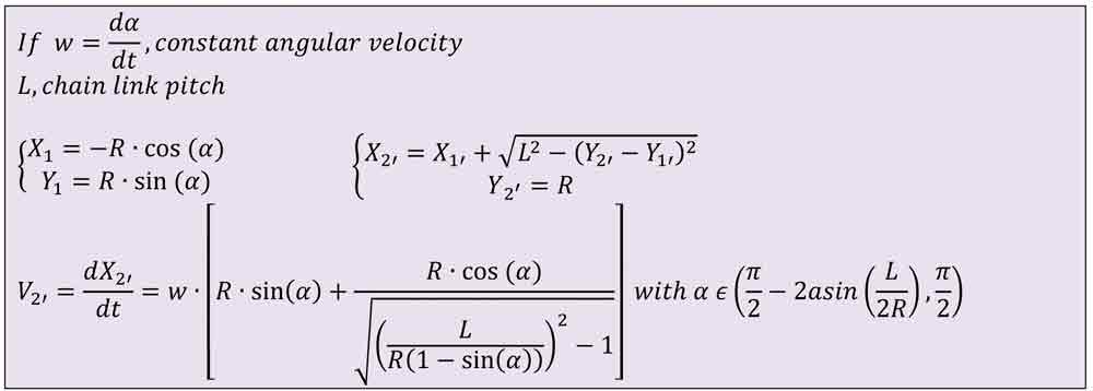
Equation 1: Linear velocity of a roller going out of the turnaround zone 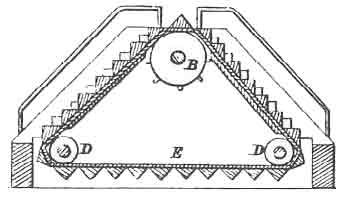
Figure 1: Revolving stairway 
Figure 2: J. Reno’s escalator 
Figure 3: Mobile skirt design (2004) 
Figure 4: Escalator drive system 
Figure 6: Static forces for different chain-link pitches 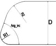
Figure 7: Parameterized turnaround 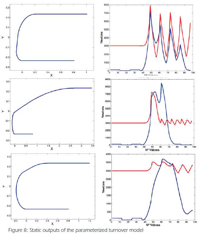
Figure 8: Static outputs of the parameterized turnover model 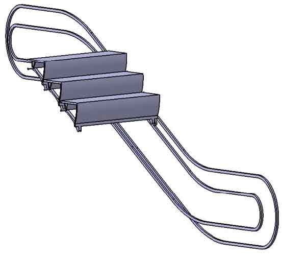
Figure 9: Conventional escalator 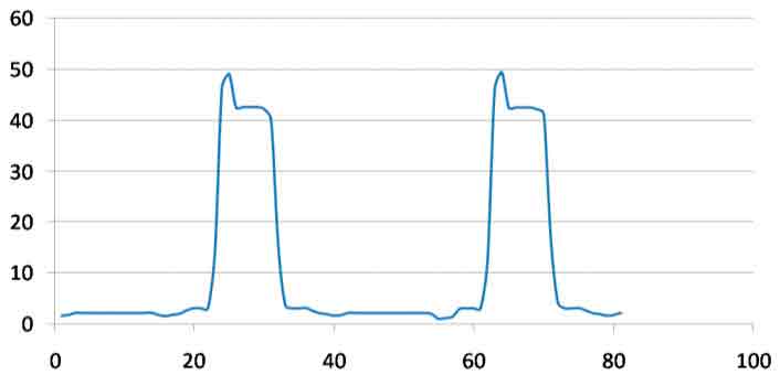
Figure 10: Minimum distance between two adjacent steps (mm) 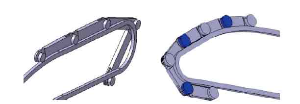
Figure 11: CATIA chain models 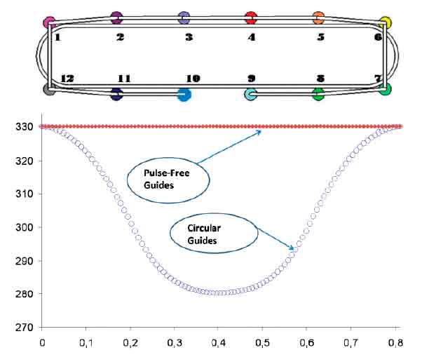
Figure 12: Chain-link elongation in circular and pulse-free guides 
Figure 13: Conventional escalator dynamic model 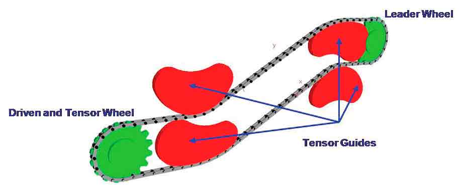
Figure 14: Main parts of a chain defined with chain modulus of SIMPACK software 
Figure 15: Roller chain implemented with basic SIMPACK software 
Figure 16: Incremental construction of time responses 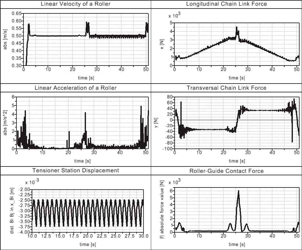
Figure 17: Main dynamic outputs of an escalator model 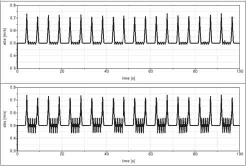
Figure 18: Best and worst cases for tensioner parameters analysis 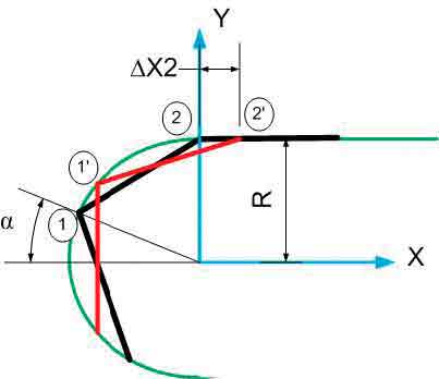
Figure 19: Polygonization-effect study in a turnaround curve 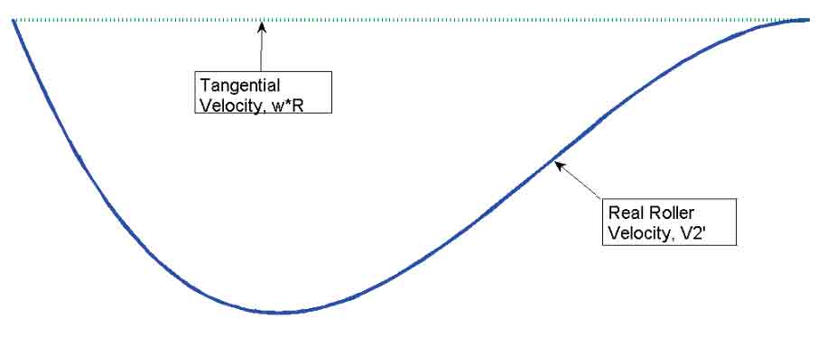
Figure 20: Velocity of a roller bearing the turnaround zone for the straight part of the guide 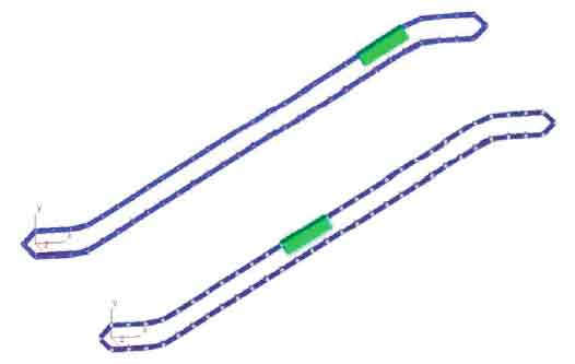
Figure 21: Roller-chain models with linear-driven systems at different heights 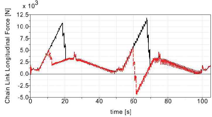
Figure 22: Chain-link longitudinal force 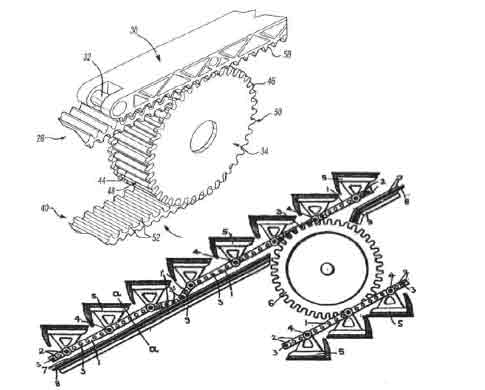
Figure 23: Linear traction systems 2002 (above) and 1918 (below) 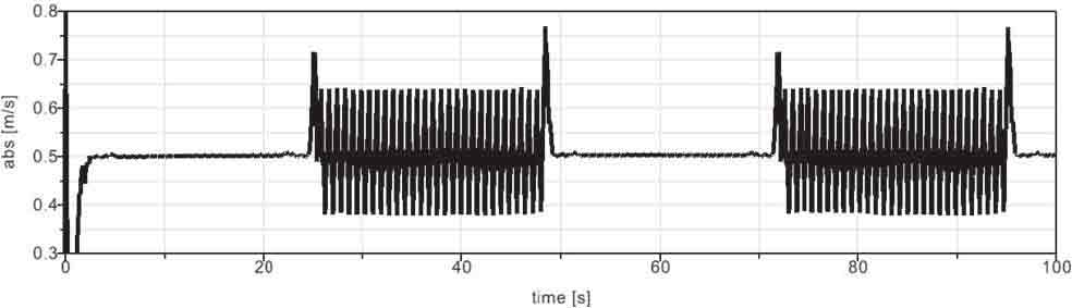
Figure 24: Linear velocity of a roller with circular turnarounds and transition zones 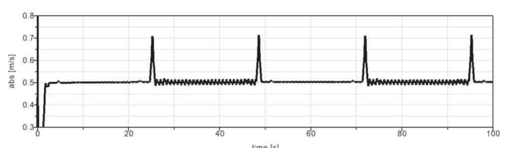
Figure 25: Linear velocity of a roller with pulse-free curves at turnarounds and transi-tion zones 
Figure 26: Chain-link longitudinal force with pulse-free guides 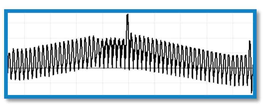
Figure 27: Chain-link longitudinal force with circular guides 
Figure 28: Chain-link longitudinal force (N) 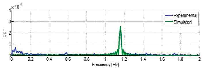
Figure 29: Tensioner-station frequency response 
Figure 30: Step vertical acceleration (mps2) 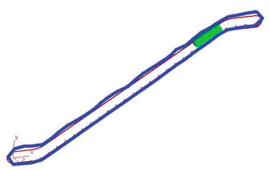
Figure 31: Roller-chain mode shape 
Figure 32: Step acceleration at 10 mps of nominal velocity for studying rollers’ lifecycle
References
[1] José María Cabanellas Becerra, Juan David Cano Moreno, Berta Suárez, José Antonio Chover and Jesús Félez, “Methods for Improving Escalators,” Elevator Technology 17: Proceedings of ELEVCON 2008, p. 22-33, 2008.
[2] José María Cabanellas Becerra, Juan David Cano Moreno, Berta Suárez, José Antonio Chover and Jesús Félez, “Advanced Dynamical Models for Escalators Simulation,” ELEVATOR WORLD, p. 136-141, 2008.
[3] Nathan Ames, “Revolving Stairways,” 28076, 1859.
[4] Charles D. Seeberger, “Aufzug mit Endloser, Spiralförmiger Transportbahn,” AT2031B, 1900.
[5] G.R. Strakosch, Vertical Transportation: Elevators and Escalators.: John Wiley & Sons, 1983.
[6] Y.S. Kwon, “Dynamic Analysis Step-by-Step,” Mechanical Engineering-CIME, 1998.
[7] Miguel Angel Gonzalez Alemany, Abdón Muñiz Camblor, José María Cabanellas Becerra and Juan David Cano-Moreno, “Escalera mecánica. Patent No. P200802887,” P200802887, 2008.
[8] Joerg Ostermeier, Helmut Meyer and Andreas Stuffel, US 2002/ 017905 A1, 2002.
[9] “Improvements in and Relating to Chain-Driven Conveyor Apparatus,” 3941/18, 1918.
[10] Juan David Cano-Moreno, José María Cabanellas Becerra, Carlos Labajo Tirado and Jesús Félez Mindán, “Methodology for Flexible Modelling of Escalator Multibody Systems,” Industrial Simula-tion Conference, Loughborough (UK), 2009.
Get more of Elevator World. Sign up for our free e-newsletter.


")
