The Street Called “Asansör” and Water-Powered Elevator Installation in Izmir
Sponsored
by Ersan Barlas, C. Erdem Imrak, Eren Kayaoglu, Adem Candas and Yusuf Z. Kocabal
Abstract
Asansör (which means elevator in Turkish) is a 1907 built building in Izmir’s Karatas quarter, within the boundaries of the metropolitan district of Konak. The old Asansör quarter, filled with old restored houses is also known as the Jewish quarter Dario Moreno Sokagi at the main pedestrian street to the Asansör itself, which is an elevator that was built in the 19th century. At fifty-one meters in height it provides access between the lower and upper streets situated on the upper side. It was built as a work of public service by a wealthy Jewish banker and trader of its epoch, Nesim Levi, in order to ease a passage of 155 steps, from the narrow coastline of Karatas to the hillside approximately 58 meters height, the elevator within the building serving to carry people and goods through the steep cliff between the two parts of the quarter. The street was renamed ‘Dario Moreno’ Street in memory of the singer. There was one water-powered elevator installations. Electrical drive machine replaced the hydraulic-powered elevator. This paper briefly presents some aspects of this old fashion elevator system and also the early applications for this type of water-powered elevators.
1. Introduction
Asansör (The Elevator), which is one of the most important historic focal points of Izmir, is a building stone in the urban identity and gives its name to the neighborhood in which it is located. The elevator made constructed by Nesim Levi, a businessman in Izmir, has connected two streets for over a century. Nesim Levi was a businessman, a Provincial Administration Councilor, owner of Bayraklı chain stores and the man who donated his house in aid of constructing Karatas Hospital, in 1907 in the quarry area. Made in conjunction with the staircase of 155 stairs the street elevator was constructed, using the technology available at that time, to enable easy access from the lower side of the neighbourhood, Mithatpasa Street to the upper side of the neighbourhood, Sehit Nihat Bey Street.
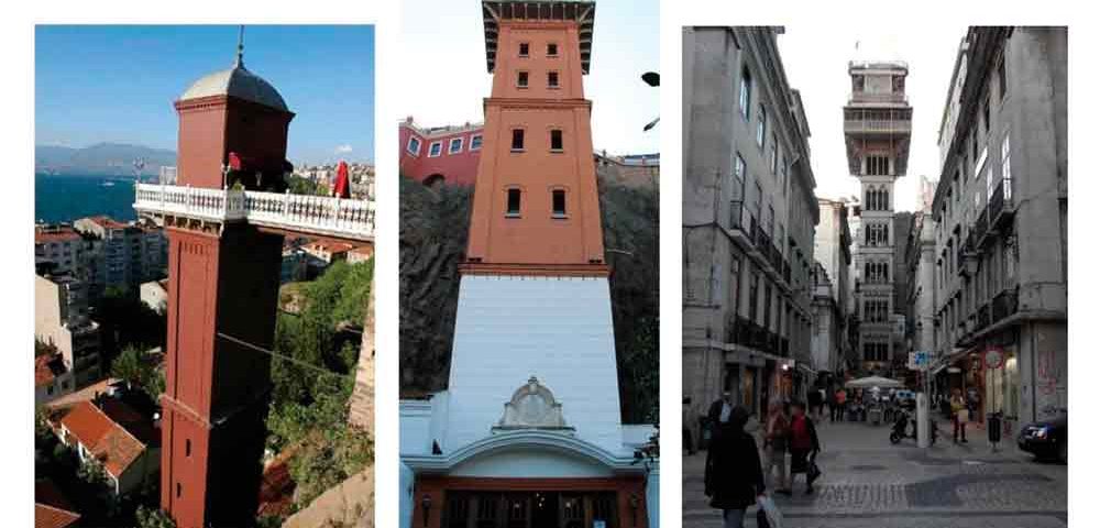
The idea and general structure of ‘Asansör’ (Figure 1a and 1b) has a strong resemblance to The Santa Justa Lift (Elevador de Santa Justa) providing a connection between the lower streets of Baixa with the higher ‘Largo do Carmo’ in Portuguese, Lisbon (Wikipedia, 2012). Santa Justa Lift was built in the same decade as Asansör, in 1901 (Figure 1c).
2. Surrounding And Architectural Characteristics
Surrounding Characteristics
The best approach in describing the structure of the Elevator (Asansör) is to take a look at the physical and social characteristics of the vicinity (Karatas and Asansör District’s textures) in which it was built.
At the end of the 19th century and the beginning of the 20th century after the construction of Halil Rifat Pasa Street and the growth of Mithatpasa Street, the area was reconstructed which resulted in the initial Jewish settlement area, focused around Havra Street and Namazgah, to slid in between Karatas-Asansör. Instead of spreading sideways the community in question chooses to stay collective in the same neighbourhood and elevated upwards. The Jewish religious building (Beth-Israel, Ros-Aar (Tepebasi), Bet-Levi Synagogues), constructed in the residential areas of the said settlement during the same period, draw plenty of attention. Karatas Hospital still exists with its modern extensions at the end of 333rd Street. The Bene-Berit Primary School, one of the community’s educational buildings, used to be opposite the Beth-Israel Synagogue but no longer exists today (Levi, 2010).
Two buildings draw attention at the Dario Moreno Street entrance (Figure 2a): To the west a two-storey apartment with a basement and a corner emphasis and to the east a two-storey house with a basement, a roof conversion and a bay window. Walking along the street it is possible to comprehend the stunning facade features of the one and two-storey houses some of which have basements, wrought iron doors, wooden bay windows, iron window sashes and the facade elements are decorated with an array of geometric and floral pattern. Besides authentic elements, altered ones are spectacular. The demolished building at the east corner of 305 and Dario Moreno Street is currently screened with engravings and photographs reflecting Izmir in historical process.
Architectural Characteristics
There is a huge amount of open space in front of the building located at the end of the Asansör culde-sac. At the building of Asansör, the entrance with three separate wooden double doors and flat sided situated on the north side of the building and accentuated by vaulted canopies simply lures people in. There are a door and two windows with flattened arch and renewed frames at the west of the entrance and a flattened arch fringed door with a window on either side at the east.
The Asansör Tower is rectangular and as you ascend to the top it narrows in levels. The bottom of the tower, which has four levels, is stone and the remainder is brick. Every brick section in the tower is separated by brick mouldings, the block corners at the top form a bulge, which makes it look like there is corner moulding. There is a plaque at the bottom of the stone part bearing the inscription “Asansör was built by Nesim Levi 1907” both in French and Hebrew which can be seen in Figure 2b. In the second and third parts overlooking the front entrance are four windows (Figure 1b) in total, each made up of two rows triangular fringed rectangular windows. There are only two windows at the top. The terrace extension rotates around the perimeter and the cast iron cantilever supporting it separates the top of the tower, which is brick fringed and crowned with a curved metal cap.
Even though the Asansör Tower has been broken away from the rocks, the locations at the top sits on the summit like an eagle’s nest as seen in Figure 3. Once the entrance of the building is comprehended, access to the hall is through the entrance door. Opposite the entrance are two elevators, to the west are the staff changing rooms, to the east there is a water pump and an operating engine room. On the elevator side of the brick walled entrance hall are stunning elements such as egg frieze, floral and star patterns that enrich the place. The top canopy of the entrance hall is an extension of the fringed entrance, has flat sides and is vault like. Entrance to the elevator, which will take you to the terrace (Figure 3) is accessible here.
Surprising views may pass in front of your eyes in the atmosphere you are in the elevator cabinet, either on your own or with others. You will open up to the outside world from the tower’s small windows when in fact a remarkable view of the Izmir Gulf and the amazing panoramic view of the city await visitors at the top, it’s almost like sitting down at a banquet table having just tasted an exquisite dish.
Once you have reached the upper altitude with the elevator you can either walk on to Sehit Nihat Bey Street or lost yourself in the different worlds at the social amenities where is a historical themed restaurant, a pub or cafeteria, formed by enclosing a part of the terrace with a simple structure. Whatever you choose to do watching poetic view which lightens up faces of those overlooking the city is inevitable.
3. Water-Powered Elevator Installation
One of the most successful types of hydraulic elevator introduced in the 1870s, and one which became a mainstay of the passenger elevator production in last quarter of the 19th century, was a hydraulic machine directly influenced by Amstrong’s crane design. These elevators employed a horizontal cylinder, piston rod, multiplying sheaves and characterized by their method of operation as either push or pull machines (Figure 4). These terms derived from the action of the piston rod on the multiplying sheaves in which one set of sheaves was fixed in place, and the second set travelled. A pull machine had both sets of sheaves located in front of the cylinder and pulled the travelling shaves away from the fixed sheaves to elevate the platform. A push machine featured the fixed sheaves at the rear of the cylinder and the traveling sheaves in front, using the piston to push them apart to transmit motion to the platform.
The hoisting cable was fastened to the top of the cylinder and passed over each sheave before rising up the shaft to connect to the platform. For example, the use of four sheaves means that for each distance the piston moved, the platform moved four times of it. Additional sheaves were installed to further increase this mechanical action. The cables attached to the hydraulic cylinder were connected, not to the platform, but to another sheave.
The hoisting cables were attached to the top of the shaft, passed under the sheave connected to the cylinder cable, and then back to the top of the shaft, over another sheave and down to the platform. Elevated tanks and force pumps were used to increase the water pressure to maintain the required force to lift the elevator cabin (Vogel, 1988).
The inventors of the early hydraulic elevators claimed the following: In hydraulic hoists of this description the stationary sheaves and the travellers have always been separated by the entire length of the actuating cylinder. According to Lane and Smith, although push machines had the advantage of being more compact than pull machines, this was their only advantage.
Because their cable passed under the cylinders as they wove between the sets of sheaves, the cables were subject to the “deleterious action” of water that often leaked out the cylinder. Push systems also required longer cables as they ran the full length of the cylinder as well as the length of the vertical run needed to raise the elevator (Figure 5).
Lane and Smith included in their design method of varying the power used depending on the weight of the load. They used two sets of travelling sheaves, one fixed to the cross head at the end of the piston rod and one set which could either be idle or linked to the first set.
For heavy loads only one set of sheaves would be used, bringing the full power of the piston into play, while lighter loads used both sets of sheaves, decreasing the piston stroke and the amount of water used (Jallings, 1995).
4. Horizontal-Cylinder Hydraulic Elevator Machine
One of the first horizontal type hydraulic machines was displayed alongside their direct-action machine at the 1872 Cincinnati Industrial Exposition. It featured a horizontal cylinder and piston, multiplying sheaves, an accumulator and was characterized as more adept in.
Horizontal-cylinder hydraulic elevator machines are divided into two classes, the pushing (Figure 7) and the pulling (Gray, 2002). In the first named, the piston is pushed out to the end of the cylinder so that the piston rod is subjected to a compression strain; in the second, the piston is moved in the opposite direction and thus the piston rod is subjected to a tensile strain.
It is desirable that the piston of a horizontal-cylinder machine be made as light as possible consistent with strength, so as to reduce the friction to the lowest point, and also for the purpose of preventing excessive wear on the lower sides of cylinder and piston. It is on this account that the follower is made in the form of a ring of light construction, and the body proper of the piston consists of an outer ring, the interior of which is closed up by a web, strongly braced by transverse ribbing.
Horizontal-cylinder machines are sometimes equipped with simple or direct-acting valves, when the speed of the car is low enough to enable the operator to control its movement with certainty by means of a hand rope. Several years ago, before car levers and pilot valves were introduced, all the elevators of this type, as well as the vertical machines, were provided with such valves, and, as there are many such machines in use at the present time, we will describe the type of valve with which they are equipped (Baxter, 1905).
Horizontal machines are always geared much higher. In vertical machines, low gears are used because there is no objection to making the cylinders long, within certain limits; but with horizontal machines there is an objection to long cylinders, as they occupy too much floor space, which in most buildings is valuable and in some cannot be had. It is for the purpose of economizing floor space that the machines are decked two and three high, and for the same reason the gear is always made greater than with vertical machines. The gears most commonly used for horizontal machines are eight, ten and twelve to one.
5. Conclusion
The system used in Asansör was a water powered push-type horizontal cylinder (Figure 6a) hydraulic elevator machine. The piston pump used in the hydraulic system was first powered by a steam engine. After some decades the piston pump (Figure 6b) remained but the steam power system was changed with an electric motor (Barlas, 2007).
The piston pump which was used to maintain pressure for the cylinder, was driven by a pulley-belt mechanism.
The stroke of the push-type cylinder is approximately 1.2 m. The height of the elevator well is nearly 50 meters. A multiplying factor provided by the sheave system for the elevation can be said as 40 times. When the piston of cylinder moved towards the direction (2), that is shown in Figure 8, the cabinet (1) of the elevator raised.
During the descending motion of the cabinet, the piston retracted slowly in order to maintain a gentle travelling. The position an representational view of the hydraulic system and the elevator well can be seen in Figure 9.
Neither the steam power system nor the original cabinet of the elevator were conservated. We could found no information about the manufacturer of the remaining hydraulic cylinder and other equipment.
After all in the end of the 20th century, the old installations gave their place to a more recent version drive system: an electric motor with a worm gear.
Acknowledgement
It is gratefully acknowledged Huseyin Cetinkaya, the old staff from “Asansör”, and Esin Hanim to help to investigate the elevator system.
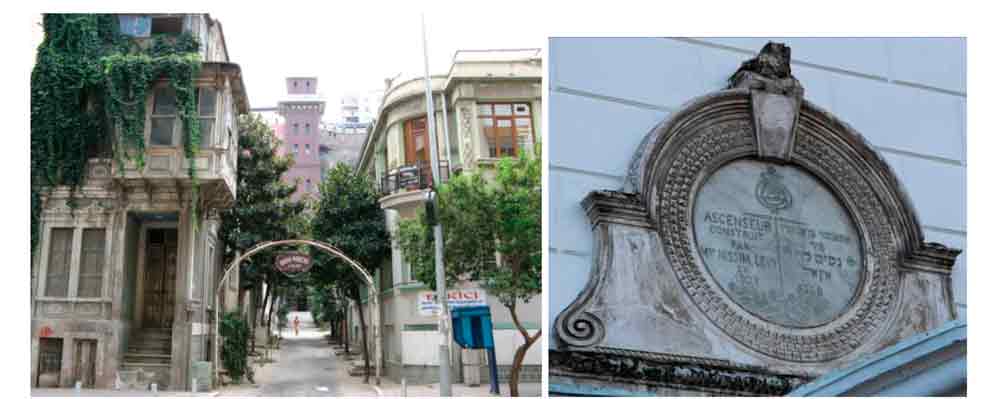
Figure 2: (a) Dario Moreno Street entrance and (b) original tablet of “Asansör” written in French and Hebrew 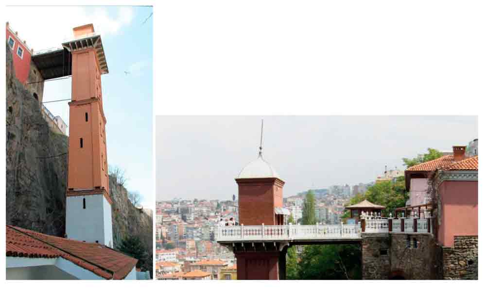
Figure 3. Asansör Tower and terrace view 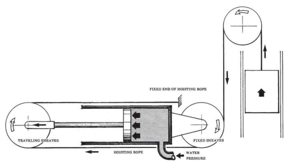
Figure 4: Principle scheme of water powered elevators 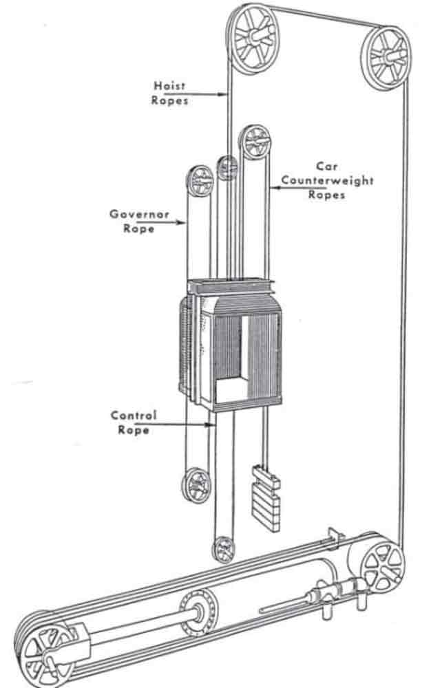
Figure 5: Principle scheme of pushing type machines 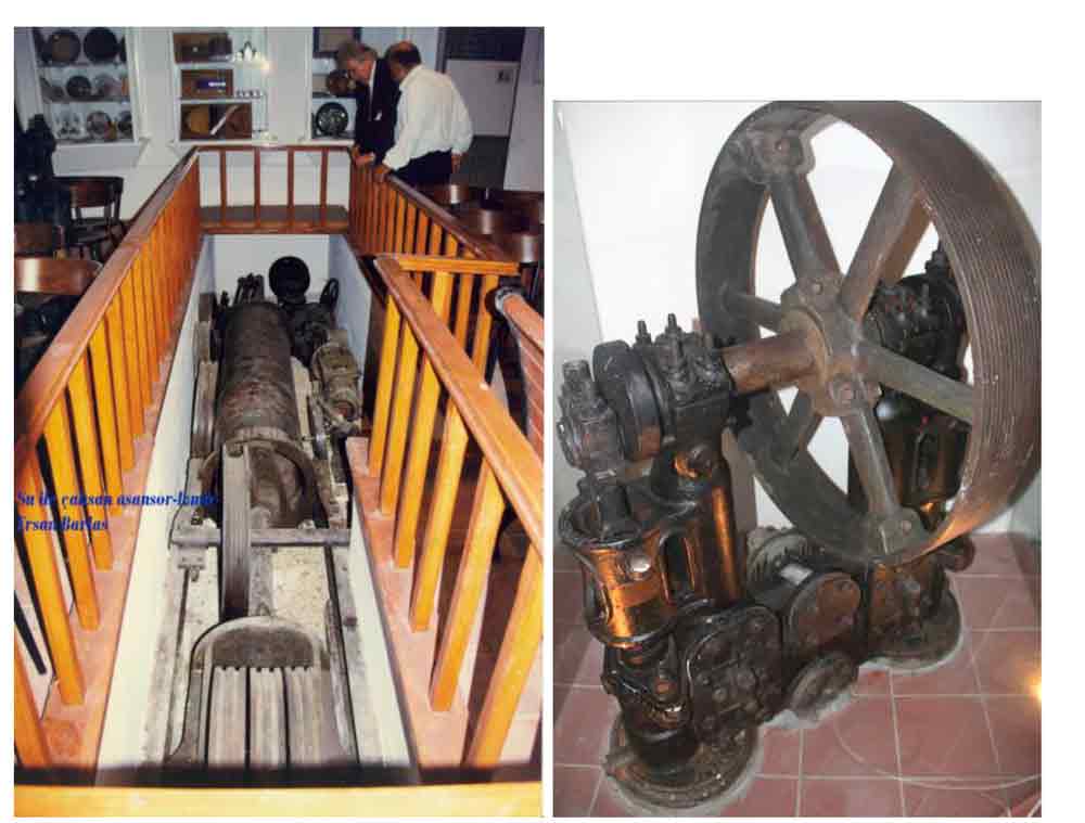
Figure 6: The remaining (a) cylinder, piston, sheaves and (b) piston pump used in “Asansör” 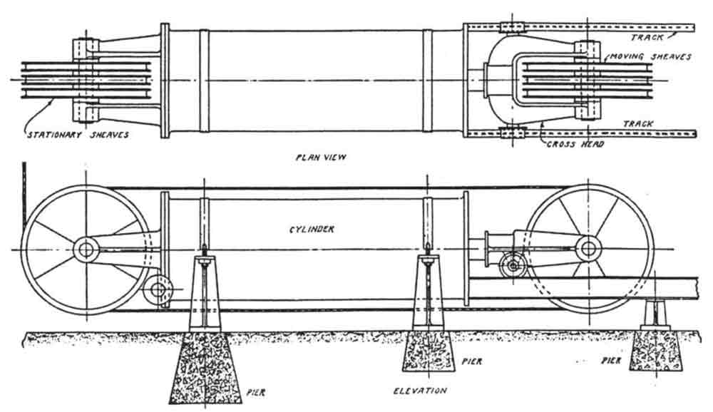
Figure 7: Horizontal cylinder “push-type” hydraulic elevator 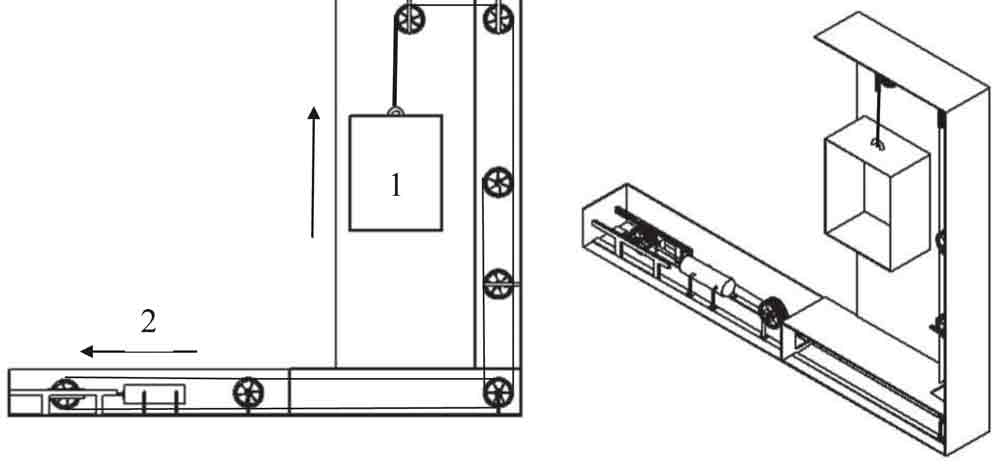
Figure 8: A sketch representing the old system 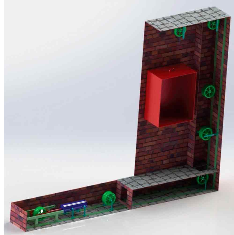
Figure 9: 3D model representation of the old system
