A 1950s Haughton Elevator
Mar 1, 2013

Haughton Elevator Co. of Cleveland often provided customers with detailed parts and maintenance manuals. These manuals were typically elevator specific: the unique machine number was typed into a designated location on the front page of each. The contents matched the elevator type and were adjusted as needed to correspond to modifications made during the elevator’s manufacture and installation.
The manual examined for this article was assembled for elevator 4448, a Haughton Type “E” electric traction elevator installed in 1959 in the University Hospitals Health Service Addition at the University of Minnesota. The manual, which includes 21 individual parts/maintenance sheets and three blueprints, provides a thorough technical description of a typical 1950s Haughton elevator. However, a careful reading of the enclosed materials – all of which are dated – reveals more than half of the features and components of this “1950s” elevator were developed in the 1930s and 1940s. The presence of “old” technology on a “modern” elevator was not unusual; engraved plaques mounted on elevator motors often listed the numerous patents that informed a specific design. Although the Haughton service manual illustrates patented systems, it also references non-patented systems, thus permitting a full examination of the blending of old and new technologies. The three blueprints also provide a glimpse into the company’s drafting room in the late 1930s.
The oldest component identified in the manual was the Haughton Type “A” Carlocator, which was the subject of two sheets (R90-1 and R90-2), both dated February 28, 1935. The car locator was a wire-driven system that consisted of a driving machine (mounted on the elevator motor), a main riser wire, individual floor wires and car-locator wheels fitted with “crystals” that indicated floor numbers. Sheet R90-1 is two sided: one side contains a section through the shaft, a detail drawing of the connection between the driving-machine steel cable and the riser wire, a detailed section of the driving machine, a partial car/shaft plan, an elevation of a typical wire connection to a hallway car-locator wheel, and two elevation drawings of typical hallway car-locator covers, which also covered the call buttons (Figure 1). The sheet’s reverse side contains detailed installation/mounting instructions and information about the driving-machine installation and adjustment, riser location, idler-sheave mounting and car locator/call-button mounting. Sheet R90-2 is single sided and contains three black-and-white photographs: two illustrate typical hallway car-locater/call-button panels, and the other shows the reverse side of one panel, illustrating the locator wheel, number crystals and call-button mechanisms (Figure 2).
Five additional parts sheets, all of which are two sided, with drawings on one side and a detailed parts list on the other, also address components designed in the 1930s:
- Care and Adjustment of Worm-Shaft Bearings (sheet R26-4, March 12, 1936)
- Haughton Type “D” Brake (sheet R2-10, May 25, 1936)
- Type “F” Interlock (sheet R94-2, April 15, 1937)
- Type “B” Retiring Cam (sheet R60-3, April 15, 1937)
- Type “T” Relay (sheet R78-2, August 2, 1938)
The parts sheet for the Type “F” Interlock is of interest for several reasons. The first is the sheet’s designation: R94-2, which implies it is the second sheet in a series. In fact, the manual does contain the companion sheet: R94-1. However, this sheet is dated May 1951. Listing the 1951 sheet as the first in the series indicates design changes or installation instructions occurred over time, while the presence of the 1937 sheet indicates the overall durability of the original design. The 1937 sheet covers both the Type F-1 Interlock (designed for single-swing doors) and Type F-2 Interlock (designed for sliding doors).
The continued use of swinging doors to access elevators in the 1930s is not surprising. However it is, perhaps, surprising to find the 1951 sheet illustrating variations of the interlock designed for left- and right-hand sliding doors, and left- and right-hand swing doors. The 1951 sheet also notes this interlock “must be used in combination with a retiring cam.” (The Type “B” Retiring Cam was designed to operate with Type “F” Interlocks).
The 1937 Type F-1 Interlock sheet also includes an elevation and section drawing of an “emergency release.” The elevation depicts the emergency-release hallway cover, which features the following warning: “Emergency door key for fire department and emergency use only.” The section depicts the emergency chain’s attachment to the door roller arm (also illustrated in the F-1 and F-2 interlock drawings in Figure 4). The release’s installation instructions are as follows:
“Drill emergency chain hole, 3/8-in. [diameter], in wall in line with hole in roller arm. Remove screws holding cover plate and glass to the mounting plate of the emergency release, and, with center hole in mounting plate over hole in wall, mark four mounting holes. Drill mounting holes for #6 rawl plugs and fasten mounting plate to wall. Cut chain to proper length and fasten it to lever arm with a cotter pin.”
The presence of an emergency door release intended for use by firefighters is a common feature of modern elevators. However, the presence of this feature in 1937 raises questions about the first use of these devices: when were they first introduced and/or required by code, and how did they operate? This topic will be addressed in a future article.
The three blueprints included in the Haughton manual all date from April 1938. Each includes the initials of the draftsman and date completed, as well as the initials of the person who “checked” the drawing and the corresponding date. (Each drawing was checked within five days of completion). All three drawings were done by “R.A.B.” and checked by “J.H.K.” The initials belong to Raymond A. Burgy (1908-1988), an electrical engineer who worked at Haughton from 1927-1973, and J. Howard Kerstetter (1900-1989), also an electrical engineer, who worked at Haughton from 1929-1964. The blueprints follow the protocol of the parts sheets and have specific letter and number designations: W-991-A (a wiring schematic of the entire installation), W-991 (a wiring schematic of the controller panel) and K-369 (a wiring schematic of the signal relay panel). Each blueprint also has a date stamp on its back that indicates when it was reproduced for inclusion in the manual; all date from November 1957. The overall wiring schematic (W-991-A) also includes a newer blueprint of the floor-selector schematic pasted over the older drawing (Figure 5). The newer print concerns the Haughton Type “FA” Floor Selector. A parts-sheet for this selector was included in the manual and is dated November 1952. It is of interest that this was the only section of the older drawing that was updated.
Each blueprint also references one of the other three: both “W” drawings note they are to be used with drawing K-369, while this sheet states it is to be used with drawing W-991. These blueprints are clearly part of a set that concerns a particular elevator type, and the fact the blueprints date from the same month and year would seem to imply the Haughton Type “E” elevator was developed in 1938. This assumption is somewhat challenged by one of the three parts sheets dating from the 1940s. Sheet R28-5, dated January 30, 1948, includes a detailed section drawing of a “Type “E” Machine Assembly” (Figure 6). However, the sheet also includes a series of references that indicate the existence of earlier drawings. The original drawing is identified as number 9019. Six “Machine Parts Lists” are also referenced and accompanied by information concerning their production and application; their probable order of development is as shown in Table 1.
Unfortunately, at this time, it is not possible to correlate a given job number with a calendar date. However, this evidence may be used to support the supposition that the Type “E” machine was designed in the late 1930s (in both an overhead and basement configuration) and that the design began undergoing modification with Job 3873. The remaining parts sheets included in the Haughton manual reference the following components in Table 2.
Of these remaining sheets, the Lubrication Chart is of interest due to its overall schematic presentation of the elevator, its thorough descriptions of system maintenance and its insistence on the use of Haughton products to ensure proper machine operation (Figure 7). The chart references the following Haughton brand Lubricants and related products: Haughton Lube Oil, Worm Gear Oil, Cup Grease, Washing Compound, Ball & Roller Bearing Grease, Motor Bearing Oil, Buffer Oil, HC Cable Compound and Cable Lubricant. The tone and detailed nature of the maintenance instructions are illustrated by the description of the proper care of motor bearings:
“Keep oil cups filled with Haughton Motor Bearing Oil. Drain bearing, flush and refill with fresh oil at least once a year. On ball-bearing motors, use Haughton Ball & Roller Bearing Grease in pressure gun: first remove plug in bottom of reservoir and fill gearing with fresh grease. Run motor at least five minutes before replacing plug so that any excess lubricant may escape.”
However, as is the case with the majority of the maintenance/repair instructions found in the manual, these assume a familiarity with elevator machinery and appear to have been written for elevator repair personnel, not for university-facilities personnel who would have had only a general training in machine maintenance.
The review of this manual serves to highlight the durability of elevator systems – the continued presence of 1930s technology in a 1950s elevator – and it prompts several questions about industry practices. These include questions about the use of naming/numbering conventions on parts sheets, the presence of dates on parts sheets and the use of blueprints to impart technical information. There is also the simple (and, perhaps, obvious) observation that these sheets represent only a small portion of what may be termed a “library” of technical data produced by Haughton. This was, of course, true of most 20th-century elevator companies. ELEVATOR WORLD readers are encouraged, as they have been in the past, to send this type of material to EW for archiving and possible future placement in the online Elevator Museum (www.theelevatormuseum.org).
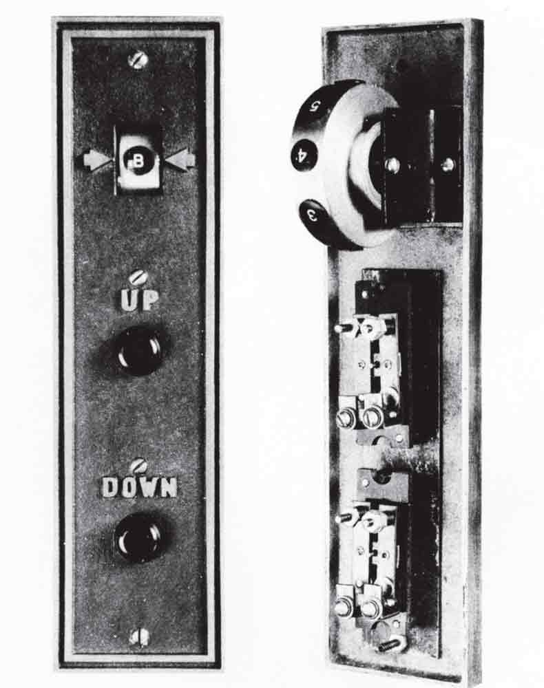
Figure 2: Front and Back of Type “A” Carlocator Panel (Haughton Parts Sheet R90-2) 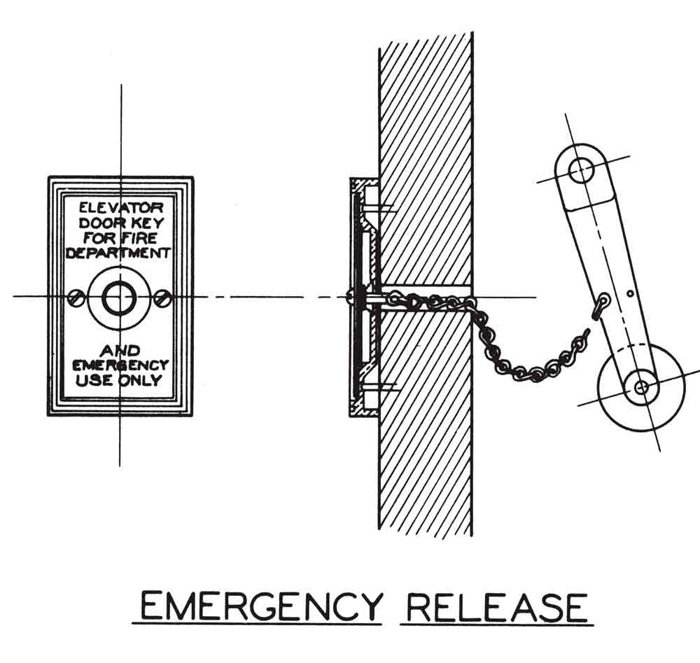
Figure 3: Emergency Release (Haughton Parts Sheet R94-2) 
Figure 4: Type F1 and F2 Interlocks (Haughton Parts Sheet R94-2) 
Figure 5: Wiring Diagram, sheet W-991-A, April 1938 (note revised blueprint pasted in upper right) 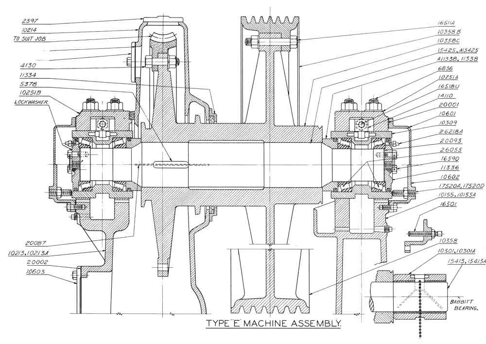
Figure 6: Type “E” Machine Assembly, sheet R28-5, January 30, 1948 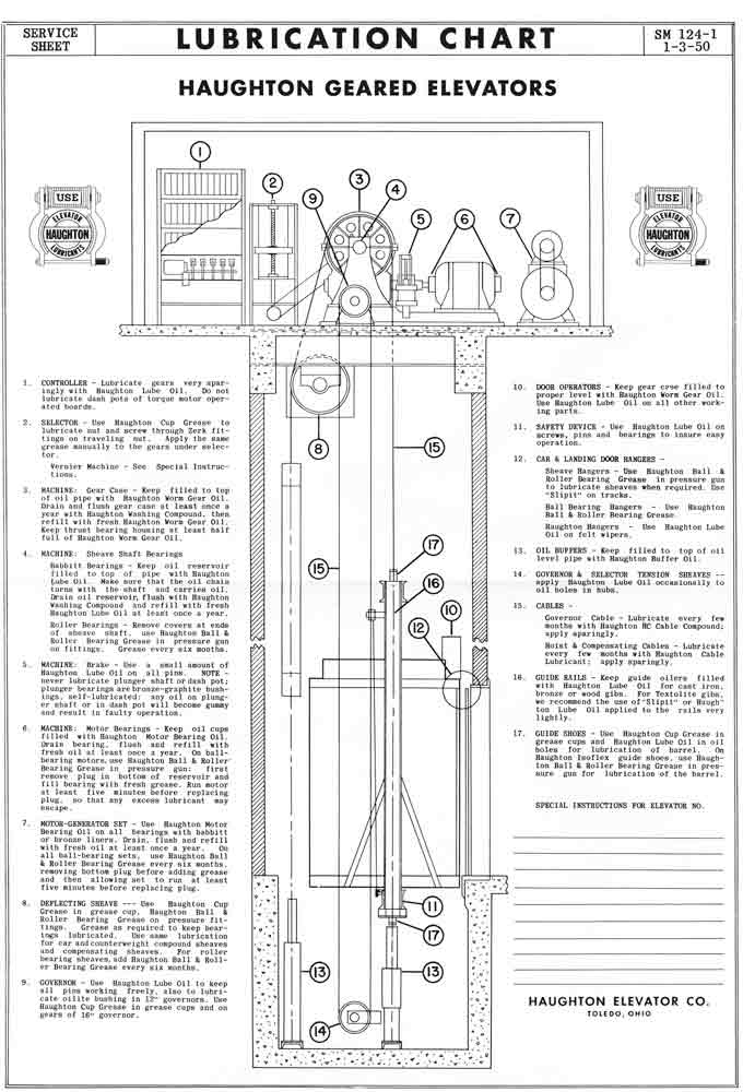
Figure 7: Lubrication Chart, sheet SM 124-1, January 3, 1950 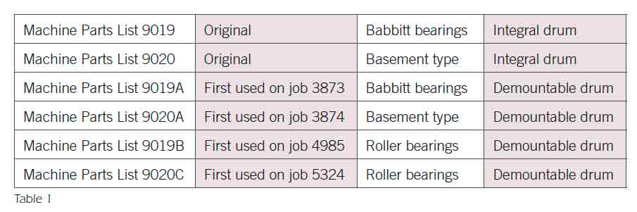
Table 1 
Table 2
Get more of Elevator World. Sign up for our free e-newsletter.


