A Biography of Reginald Pelham Bolton, Part 2
May 1, 2017
The subject’s career as a consulting engineer is the topic of this segment.
When Reginald Pelham Bolton arrived in New York City (NYC) in 1894 to launch his engineering consulting business, he found himself immersed in a dynamic architectural and engineering environment focused on the continued development of the skyscraper. However, this activity took place in a challenging economic setting. The financial panic of 1893 had plunged the U.S. into a depression that lasted throughout the remainder of the decade, with unemployment rates estimated at more than 10% per year until 1900. In spite of this less-than-auspicious backdrop, Bolton quickly established himself as one of the city’s leading consulting engineers specializing in the design of mechanical systems for tall buildings.
Given the character of his prior engineering career (ELEVATOR WORLD, April 2017, “A Biography of Reginald Pelham Bolton, Part 1”), which did not involve work on large-scale building projects, it is uncertain how Bolton marketed his alleged engineering expertise. What is known is that Bolton apparently possessed a remarkable sense of confidence in his ability to solve almost any engineering problem. In fact, upon his arrival in the U.S., Bolton pursued three parallel careers: a consulting engineer, prolific author of technical papers and articles, and well-known and respected amateur historian and archaeologist of the colonial and Native American history of Manhattan and its surrounding region.
A biographical sketch published in Engineering Review in 1910 described Bolton as having made a “specialty [of] the inter-relation of the entire steam, electrical, elevator, sanitary and other systems, and particularly developing the harmonious design of piping for services.”[1] This statement implies that Bolton approached the design of mechanical systems in an integrated manner, rather than as the assembly of discrete components. The sketch’s author also credited him with several:
“. . . departures from ordinary practice, which he successfully introduced, such as the first use of unlined conduit, the vertical system of electrical wiring, the utilization of open feed heaters, the first applications of the vacuum system to heating plants, the introduction of the multiple-pressure drum system on fire and house water supplies, and the first utilization of the duplex pressure system of elevator operation.”[1]
The last item, the duplex pressure system of elevator operation, was designed by Bolton for use in the Bowling Green Building in 1895. This system, which employed low- and high-pressure tanks to power hydraulic elevators, was described in “Early Elevator Plants in New York City” (EW, January 2013). Its rationale derived from Bolton’s observations of typical elevator operation:
“The consideration which led to its design was the fact that the schedule service of such a building develops an average load, and that the number of trips in which the load exceeds the average is but a small fraction of the whole. By designing the cylinders to carry only loads not exceeding the average load with the usual pressure, a great saving of pumped water could be effected on the greater part of the work, while a reserve of water under a higher pressure could be admitted to deal with loads exceeding the average, up to the maximum load.”
While he was not the first to propose a system that provided variable power depending on the carried load, he appears to have been one of the first to base this design decision on the observation of elevator use patterns.
Twenty buildings, built between 1895 and 1910, have been identified as projects for which Bolton was engaged as a consulting engineer. For 11 of them, it has been possible to identify the elevator manufacturers (Table 1). This project set reveals that Bolton participated in projects that involved well-established elevator manufacturers and systems, as well as newcomers promoting innovative systems: Otis and its vertical hydraulic machines (developed in the 1870s), Sprague Electric Elevator Co. and its electric screw-driven machine and the massive direct plunger machines built by Standard Plunger Elevator Co. A critical question that remains largely unanswered concerns the precise role Bolton played in designing the elevator systems of these buildings.
One of Bolton’s first projects was the Syndicate Building (later known as the German-American Bank Building) in NYC. Electrical World magazine described the building as:
“. . . in every sense of the word, one of the most complete modern office structures ever erected. From an electrical and mechanical standpoint, it presents many features of extreme interest to the engineer. The steam and electrical equipment are as perfect as human skill and ingenuity can make them, and it is stated by Mr. Reginald Bolton, the consulting engineer of the building, that these plants are the most economical ever placed in a building of this character.”[2]
The magazine also provided a detailed description of the building’s elevators:
“The building is provided with five Sprague-Pratt multiple-sheave screw electric elevators, two being double decked, or mounted one on top of the other, thus greatly economizing in space. Each is geared 16 to 1, and designed to lift a maximum load of 2500 lb. in the car at a speed of 500 fpm and to meet the requirements of a 22-story building in case the present intention of adding seven more stories is carried out. Apart from the Postal Telegraph Building, which was fitted with the original form of these machines, the Syndicate Building is the first large New York office structure to adopt the electrical elevator on a scale of five machines. . . . The motors used in the Sprague machines are of the multipolar type. The field magnets are of steel, and are excited by two circuits, one known as the shunt circuit, being variable in strength at will, so as to vary the maximum speed of the machine, and the other a series circuit, which acts to strongly compound the field. In hoisting, the motor takes current from the line, but in lowering, its main circuit is cut off from the line and the motor, rotating in the opposite direction, [and] is driven as a dynamo by the weight of the car. The fact that the current in the field coils is never reversed, and in consequence, the machine is never demagnetized, forms a strong element of safety.”[2]
This description, which refers to the Postal Telegraph Building as equipped with “the original form” of the Sprague-Pratt elevator, clearly implies that the Syndicate Building employed a modified design. This idea is supported by Bolton’s claim, made in 1901 in a paper presented to the British Institution of Civil Engineers, that the Syndicate Building’s elevators featured “certain improvements” of his own design.[3]
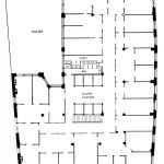
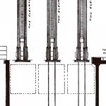
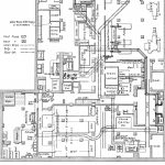
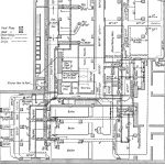
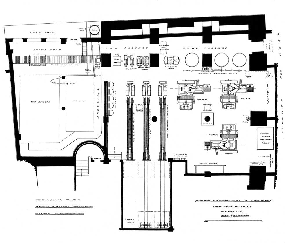
Although no details regarding Bolton’s “improvements” have survived, sufficient information remains that illustrates the complexity of the building’s engineering challenges. The plan of a typical upper floor reveals the elevator placement with two three-car elevator banks facing each other (Figure 1). When the building opened in 1896, only five shafts contained elevators. (The sixth elevator was added in 1899.) The plan of the building’s mechanical room reveals the overall character of the space and the size of the Sprague-Pratt elevator machines, each of which was more than 25 ft. long (Figures 2 and 3). As was noted in Electrical World’s description of the installation, two sets of machines were arranged in a double-deck fashion to save space (Figure 4).
The plan of the Syndicate Building’s mechanical room, which may have been drawn by Bolton, is a relatively sparse, and perhaps somewhat incomplete, representation of the mechanical systems required to support a tall building. However, another Bolton project, the Lorraine Hotel Building in NYC (completed in 1900) permits greater insight into the engineering challenges presented by tall buildings. The hotel had 13 above-grade floors, a basement and a subbasement. The building’s elevator equipment was described as consisting of two passenger elevators, two freight elevators, two sidewalk elevators, one ash hoist and two dumbwaiters. The passenger and freight elevators were Otis’ vertical hydraulic elevators and were described as follows:
“The passenger cars have a maximum live load capacity of 2500 lb. lifted at the rate of 225 fpm and an average load capacity of 800 lb. at 300 fpm. They are designed to make the total lift of 153 ft., 6 in. in [a] 1-min. round trip, averaging 5 mph. The freight elevator has a capacity of 3000 lb. at 150 fpm. . . . The pumping plant is in triplicate, consisting of three Worthington compound pumps. . . [producing an] average pressure of 125 psi. The elevator tank is of the ordinary double-headed horizontal cylinder type.”[4]
Although a typical upper floor plan has, apparently, not survived, plans depicting the building’s basement and subbasement exist that permit an examination of the various mechanical systems. The basement plan indicates the location of the passenger and freight elevators, as well as the dumbwaiters (Figure 5). Two versions of the subbasement plan exist: one that primarily addresses the overall organization of the mechanical spaces, plumbing and various hotel functions housed on this floor, and one that addresses the building’s ventilation and steam piping systems.
A comparison of the basement plan with detailed views of the two subbasement plans illustrates the interconnections of the various systems and raises several questions. The passenger elevators did not operate past the basement level, while both freight elevators ran to the subbasement. One of the subbasement plans clearly depicts the location of the primary components of the elevator system: pumps, pressure tank, surge tank and the vertical hydraulic machines of the passenger and freight elevators and sidewalk elevators (Figure 6). This plan also reveals a smaller fifth elevator behind the passenger elevators, which is not found on the basement plan. The second subbasement plan illustrates the building’s ventilation system and labels two of the primary elevator shafts a “elevator shaft to roof” and “elevator cylinders in light shaft, vent to roof.”[4] A careful reading of the subbasement plans reveals some intriguing discrepancies between the systems shown on the basement plan and between the systems depicted on the two (allegedly identical) subbasement plans.
Bolton was credited with designing the building’s mechanical plant, plumbing system and, interestingly, kitchen. While the Otis hydraulic elevators did not utilize his duplex pressure system, he appears to have designed a unique system feature. The Westinghouse air compressor that supplied compressed air to the elevator tank and the “pressure drum system” that provided pressure for the building’s water system was also used to force water into a 1/2-in. pipe that ran inside the elevator shafts. The pipe had outlets on each floor with hose connections that permitted “easy cleaning of the elevator grille work.”[4] The utilitarian characteristics of this additional feature reflect Bolton’s pragmatic approach to mechanical system design and his attitudes toward the use and application of vertical-transportation systems. The conclusion of this biography will further explore Bolton’s approach to elevator design as seen through an examination of his extensive writings on this topic.
- Figure 1: “Typical Upper Floor Plan,” Syndicate Building, NYC (1896)
- Figure 2: “Mechanical Room Plan,” Syndicate Building, NYC (1896)
- Figure 3: “Detail Plan of Mechanical Room Plan,” Syndicate Building, NYC (1896)
- Figure 4: “Elevator Machines,” Syndicate Building, NYC (1896)
- Figure 5: Partial basement plan showing elevator and dumbwaiter location, Lorraine Hotel-Apartment Building, NYC (1900)
- Figure 6: Partial subbasement plan showing elevator piping and machinery, Lorraine Hotel-Apartment Building, NYC (1900)
- Figure 7: Partial subbasement plan showing ventilation scheme, Lorraine Hotel-Apartment Building, NYC (1900)
- Table 1: A partial list of OEMs for projects in which Bolton was engaged (1895-1910)
References
[1] “Reginald Pelham Bolton,” Engineering Review, December 1910.
[2] “The Electrical Plant of the Syndicate Building, New York,” Electrical World, August 29, 1896.
[3] “High Office Buildings of New York,” Minutes of Proceedings of the Institution of Civil Engineers With Other Selected and Abstracted Papers, London: 1901.
[4] “The Mechanical Plant of a Large Apartment Building,” Engineering Record, October 27, 1900.
Get more of Elevator World. Sign up for our free e-newsletter.
