Outlining existing problems in A17.1 and EN 81-20
by Guangchi Liang
Modern elevator safety highly depends on the elevator braking capacity. Braking failure will lead to car overspeed or unintended car movement (UCM) with the car door open, increasing the risk of death or serious injury to an unacceptable level. Of the more-than-6-million elevators operating in China, the number of accidents caused by braking failure ranks second behind those caused by door failure, while the severity ranks first (Figure 1).
In recent years, although new elevators have added ascending car overspeed protection (ACOP) and UCM protection (UCMP) based on existing downward overspeed safety gear protection, the increased protection function still relies on adequate and reliable braking capacity from redundant or relatively independent brakes. Adequate and reliable braking capacity is still one of the most important guarantees for elevator safety. However, the braking capacity of the elevator is not the greater, the better: too much braking torque will lead to too-fast car deceleration, which can cause passengers to be injured.
This article discusses the requirement of braking capability and the existing problems in two major elevator safety standards — ASME A17.1 and EN 81-20. The influence of other elevator braking devices, including safety gears, is also discussed.
Requirements of Current Standards for Braking Capacity
In A17.1-2013, for passenger elevators, braking capacity requirements are summarized as follows:
a. The minimum braking capacity requirementThe braking system can decelerate the car from its rated speed when it is carrying its 125% rated load in the down direction, or empty car in the up direction from the speed at which the governor overspeed switch is set. The allowable buffer striking speeds are considered, and the loss of main line power shall not reduce the braking system capacity below the requirements stated here (2.24.8.2.2).
1. The driving machine brake can hold the car at rest with its 125% rated load, and decelerate the empty car traveling in the up direction from the speed at which the governor overspeed switch is set, ensure that the impact speed of the buffer is below its allowable value (2.24.8.3).
2. The emergency brake can decelerate, stop and hold the car with any load up to 125% rated load (2.19.1.2(b), 2.19.2.2(b)). The emergency brakes shall also meet the other braking requirements of ACOP and UCMP.
b. Maximum braking capacity requirement: the car average deceleration produced by the Braking System (including machine brake or in combination with electrically assisted braking but not the emergency brake) is not more than 9.8 m/s2 (32.2 ft/s2) (2.24.8.2.2). The emergency brake does not on its own cause the car average retardation to exceed 9.8 m/s2 (32.2 ft/s2) during the stopping or slowdown phase during ascending car overspeed (2.19.3.2(h)).
In EN 81-20:2014, for passenger elevators, braking capacity requirements are summarized as follows:
The driving machine brake on its own shall be capable of stopping the machine when the car is travelling downward at rated speed and with 125% rated load.
All the mechanical components of the redundant machine brake (RMB), which take part in the application of the braking action on the braking surface, shall be installed at least in two sets. If one of the brake sets is not working due to failure of a component, there is sufficient braking torque to decelerate, stop and hold the car when traveling downward at rated speed and with rated load in the car, or upward with empty car (5.9.2.2.2.1).
2. When the RMB is a brake for ACOP and UCMP, the braking capacity requirements of ACOP and UCMP are for the whole redundant Machine brake, rather than considering the failure of single brake components (5.6.6, 5.6.7).
When the driving machine brake on its own stops the elevator downward at rated speed and with 125% rated load, the average retardation of the car shall not exceed that resulting from operation of the safety gear or stopping on the buffer.
For ACOP and UCMP, during the stopping phase, the stopping element of the means shall not allow a retardation of the car in excess of:
a. 1gn in the up direction with an empty car
b. The values accepted for devices for protecting against freefall in the down direction.
In China, most of the 700,000 elevators manufactured each year consist of permanent-magnet synchronous motors. These elevators basically adopt RMBs as brake components of ACOP and UCMP.
Problems of Current Braking Capacity Requirements
The requirement that the driving-machine brake be able to stop the car traveling downward at rated speed and with 125% rated load in EN 81-20 is too low after RMB application. As shown in Table 1, when the balance coefficient is 0.5, if one of the two brake sets fails, the brake can only hold 87.5% rated load. On the other hand, if one of the braking components fails, the braking capacity requirements for deceleration, stopping and holding the downward car with 100% rated load in EN 81-20, Section 5.9.2.2.2.1, is obviously insufficient, because the elevator is still allowed to operate within 110% of the overload under the requirements of Section 5.12.1.2.2.
When the RMB serves as a brake for ACOP and UCMP, it is possible that the current ACOP and UCMP will fail due to insufficient braking capacity if one of the brake components fails. In EN 81-20, Sections 5.6.6, 5.6.7, the braking capacity requirements of ACOP and UCMP are for the whole RMB and do not consider the failure of single brake components.
As can be seen above, in A17.1 and EN 81-20, the braking capacity of the machine brake and emergency brake are required only from ratio of rated load (k). It is a problem that the
safety margin (Sa) of the brakes is different under the same rated load ratio (k) with different parameters like equilibrium coefficient (q).

The safety margin of braking torque (Sa) is like a safety factor used to ensure the brake itself is still safe under some uncertainties (cold and hot, dynamic and static, before and after wear, etc.). A suitable stable Sa is a key to ensure the safety and reliability of braking capacity. A k does not guarantee a stable Sa.
The relation between Sa and k, depending on multiple parameters (static state), if perfect compensation is assumed and regardless of the mass of the traveling cable, is:
Sa = (p + kQ – mcwt)/(p + Q – mcwt) = (k – q)/(1 – q) (2)
where Sa is the safety margin of braking torque; k is rated load ratio; Q is rated load; P is mass of empty car; and q is the equilibrium coefficient, indicating the amount of counterbalance of the rated load by the counterweight; and mcwt is the mass of the counterweight (P + qQ).
In A17.1, when the emergency brake acts on the working surface of the machine brake, and the two brakes are operated at the same time, if q = 0.5, k = 1.25 and Sa = 1.5 for each brake,
for two brakes (Sa = 3), the two brakes can hold 200% rated load (k = 2). In the same situation, if q = 0.4, k = 1.25 and Sa = 1.42 for each brake, for two brakes (Sa = 2.84), the two brakes can hold 210% rated load (k = 2.1) (Table 1 and Figure 2(a)).
In EN 81-20, if one of the brake components fails, and q = 0.5, k = 1 and Sa = 1, the whole RMB can hold 150% rated load (equivalent to Sa = 2 and k = 1.5). If one component fails, and q = 0.4, k = 1 and Sa = 1, the whole brake can hold 160% rated load (equivalent to Sa = 2 and k = 1.6). But, if one of the brake components fails, there is not enough braking capacity to decelerate, stop and hold the downward car with 110% overload allowed to operate per EN 81-20. This is clearly not redundant and thus unacceptable (Table 1 and Figure 2(b)).
In your author’s opinion, besides k, Sa should be required as in Figure 3. This is especially true if q value is not required in the standard(s). If there is an Sa requirement, k can be reduced appropriately.
In China, there is another elevator traction machine standard (GB/T 24476-2009) that requires braking torque negotiated with traction machine users in accordance with GB 7588-2003 (EN 81-1:1998), or 2.5 times the rated torque converted to the braking wheel (disc). This equivalent to Sa is 2.5 for the whole RMB, and after one of the braking components has failed (and there are two braking components), Sa = 1.25.
Therefore, suggestions in preparation of China elevator safety technical regulations are as follows:
- As Figure 3(a) and Table 1 show, if one of the two braking components fails, the braking capacity can decelerate, stop and hold 110% rated load car at rated speed, equivalent to Sa = 1.17 (q = 0.4) to 1.2(q = 0.5). The whole RMB can hold 170% (q = 0.5) to 180% (q = 0.4) rated load.
- As Figure 3 (b) and Table 1 show, if one of the two braking components fails, the braking torque safety margin Sa is not less than 1.25, equivalent to k = 1,125 (q = 0.5) to 1.15 (q = 0.4). The whole RMB can hold 175% (q = 0.5) to 190% (q = 0.4) rated load.
These recommendations are in place of the driving machine brake being able to hold 125% car rated load, and the emergency brake being able to decelerate and hold the car
with any load up to 125% rated load (A17.1) or the braking capacity to decelerate, stop and hold the downward car with 100% rated load when one of the brake components fails (EN 81-20). That is, after the failure of one of the braking components, the braking capacity recommendation is k ≥ 110%, and Sa ≥ 1.25.
The Influence of Multiple Brakes on Elevator Deceleration
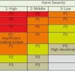
The hazard analysis of excessive deceleration of multiple brakes is shown in Table 2. Risk-level analysis is shown in Table 3.
Analysis Result
- Upward: Any car deceleration exceeding 9.8 m/s2 (32.2 ft/s2) is not acceptable.
- Downward: Any car deceleration exceeding the maximum deceleration of the safety gear action is not acceptable.
- In the A17.1 and EN 81-20, there are only deceleration requirements for each brake acting alone. There is no deceleration requirement when multiple brakes (driving machine brake, emergency brake, electric brake and safeties) are operating simultaneously.
Multiple Brakes With Simultaneous Downward Action
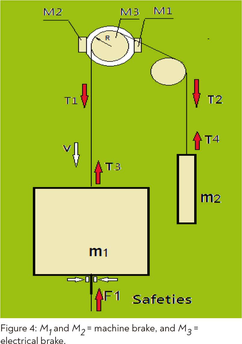
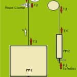
In the simultaneous action of the machine brake, electric brake, emergency brake and safeties downward (as in Figure 4), there are two situations to consider:
1) For flexible transmission, once the wire rope is relaxed, the force between the two ends of the rope will not superposition.
2) For friction transmission, the transmission force is limited by friction slip.
For the machine:
M1 + M2 + M3 – M4 = J (3)
For the car:
F1 + T3 – gm1 = a1m1 (4)
In Eqs. 3 and 4, M1 is machine brake torque; M2 is emergency brake torque; M3 is braking torque generated by star sealing electrical braking or another electrical brake; M4 = R(T1 – T2); ![]() is angular acceleration of the traction wheel;
is angular acceleration of the traction wheel; ![]() J is the machine’s rotational inertia; F1 is the safeties’ braking force; R is the nodal circle radius of the traction wheel; a1 is car acceleration; and m1 is car mass.
J is the machine’s rotational inertia; F1 is the safeties’ braking force; R is the nodal circle radius of the traction wheel; a1 is car acceleration; and m1 is car mass.
If the deceleration produced by the machine brake is greater than that produced by the safety gears, the rope between machine and car is tense, and the deceleration will be superimposed. Fortunately, the possibility of such a situation is not too great, because brakes generally produce less deceleration than safety gears do. Also, even if this happens, this example is in the case of larger machine brake torque, which will be limited by friction slip between traction wheel and rope. However, we should consider the danger of deceleration superimposition. Especially in recent years, the compromise of traction conditions does not require slippage in detention conditions, which increases the chance of deceleration superimposition.
Under special circumstances, it is still possible that when machine brakes, electric brakes, emergency brakes and safety gears are operated simultaneously, the braking torque (force) will be superimposed, as will the braking deceleration of the car. Therefore, the car deceleration caused by the possible simultaneous action of various brakes shall meet the following requirements:
- For upward movement, car deceleration is not more than 9.8 m/s2 (32.2 ft/s2).
- For downward movement, car deceleration is not more than the maximum value of safety gear action. (Class A safety gear action needs to be considered.)
Simultaneous Upward Action of Multiple Brakes
Simultaneous action of the machine brake, electric brake, rope clamp (emergency brake) and safeties of counterweight when upward is depicted in Figure 5. Multiple-brake simultaneous action is similar downward.
Conclusion
For passenger elevators, your author recommends the following for braking capacity:
- Rated load ratio: k ≥ 1.1: if one of the two braking components fails, the braking capacity can decelerate, stop and hold 110% of the rated car load at rated speed.
- Braking torque safety margin: Sa ≥ 1.25. If one of the two braking components fails, the braking torque safety margin Sa is not less than 1.25.
For the influence of multiple brakes on elevator deceleration, under special circumstances, the braking torque of multiple elevator brakes may be superimposed at the same time. This increases the deceleration of the car, thus causing harm to passengers. Especially when modifying an elevator with RMB with a rope clamp, not all braking forces are superimposed. Nor are they superimposed when the wire rope is loose. In addition, traction friction slipping also limits the influence of machine braking force on the car. It is necessary to limit the car deceleration in this case. For upward movement, your author recommends car deceleration not more than 9.8 m/s2 (32.2 ft/s2). For downward movement, your author recommends car deceleration not more than the maximum value of the safety gear action.
The braking capacity is not “the bigger, the better,” nor should it be “just right.” Insufficient braking capacity can cause death or serious injury. A certain safety margin is needed. In some special cases, care should be taken that multiple braking forces may be superimposed. The braking capacity problem needs to be handled carefully.
- Figure-1
- Figure-2-a-b
- Figure-3-a-b
- Figure-4
- Figure-5
- Table-1
- Table-2
- Table-3
Get more of Elevator World. Sign up for our free e-newsletter.
