
How to identify and prevent traction sheave damage due to unequal rope tension
Value: 1 contact hour (0.1 CEU)

This article is approved for Continuing Education by NAEC for CET® and CAT®.
EW Continuing Education is currently approved in the following states: AL, AR, FL, GA, IL, IN, KY, MD, MO, MS, MT, OK, PA, VA, VT, WV and WI. Please check for specific course verification of approval at Elevator Books.
Learning Objectives
After reading this article, you should have learned about:
- Steel wire rope diameter and traction groove depth must be included in maintenance tasks with a minimum of annual verification.
- When any sign of ground particles is visible near the driving machine sheave, the system must be tested for rope equalization, and the ropes must be equalized to stop the destruction.
- Equal tension is when the difference between the highest rope tension is within 10% of the lowest rope tension.
- Verify that steel wire rope anti-rotation devices are incorporated in the suspension system.
- Recording tools should be used to document the actual change in rope tensions to determine the cause.
The traction system is critical to the elevator system. Its two interrelated components, suspension members and the traction sheave, have tremendous safety and cost considerations. Degradation of the sheave and rope relationship can have very expensive ramifications for owners and is an integral maintenance item that should be corrected before mandatory replacement of the sheave and ropes becomes necessary. Degradation left unchecked causes the worst type of incident: loss of traction and, therefore, uncontrolled car movement (UCM). Once broken, the out-of-balance elevator/counterweight can accelerate uncontrolled to the terminal, the end of the travel path.
The ASME A17.1/CSA B44 Safety Code for Elevators and Escalators has traction design requirements, traction maintenance and testing, overspeed, and UCM protection in both the up and down directions to ensure this relationship remains stable and in compliance.
Abnormal wear and tear, combined with the infrequency of proper maintenance by mechanics/technicians, is increasing. This is evidenced by the number of damaged sheaves being seen in the field. In some sectors of the vertical-transportation maintenance world, reliance on electronic fault detection systems that provide early warning of misoperation or failure is becoming the norm. This appears to be reducing the technical understanding of mechanical systems by maintenance personnel to simply respond to a “check engine light” that another page in a book will describe as “what to do in case of” or to simply write a note to notify a superintendent or the office for further instructions. Many of these fault detection systems cannot detect the traction system degradation to prevent this loss of equipment. One exception is the Henning GmbH & Co. KG WEARwatcher®.
If signs of degradation are not addressed early by trained and active maintenance personnel, the owner’s sheave and/or suspension ropes can degrade to the point of requiring replacement long before their design life. This is typically at the owner’s expense.
This article is intended to illustrate what we have seen in the field, how this problem should be addressed by maintenance companies and owners, what the code intends and how technology can be used to maximize both safety and equipment life.
The Problem
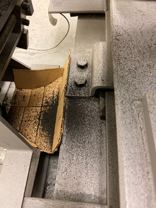
Figure 1 shows the accumulation of magnetic, steel particles under the counterweight-side pinch point of a geared traction driving machine. The elevator has a maximum speed of 1.75 m/s (350 ft/m), 11 stops, a front entrance only, runs an average of 1,700 times a day and is only seven years old. It is one of a triplex of units, yet the others (with same duty) do not show this loss of sheave material. What is the difference?
The owner was advised the sheave needs to be replaced, but determining who is responsible for the damage (absent finding the exact cause of the material loss) is a challenge. The maintenance company asserts the materials are defective; the manufacturer asserts the maintenance company is responsible. Finding the cause of this destructive action became the goal. This article explains what was occurring in this situation and how to stop it, when possible.
This story begins by trying to reduce and eliminate the low-hanging fruit of maintenance expenses, callbacks, using WEARwatcher as a telemetry system to provide elevator information that can be obtained immediately via the cloud. Callbacks reduce efficiency of the elevator and remove labor from maintenance. Imbedded in their sum is a percentage of “Running on Arrival” (ROA) callbacks. These are the time- and money-wasting calls in which, when the technician arrives, the unit is running. It is tested, rode and documented as ROA. ROAs account for 36% of all callbacks in a large population of more than 600 mixed units using eMCP® as their maintenance control program (MCP). That accounts for a lot of inefficient use of labor, wasted owner expense, lost maintenance time, etc.
Many companies have ideas about how to reduce these inefficiencies. eMCP is incorporating telemetry devices to determine unit condition to safely decide if the callback report is a potential ROA or a real callback. Careful evaluation of the ride profiles and predictable motions provides information that can ultimately be used to determine, along with a mechanic’s judgment, if a callback is needed. eMCP integrates WEARwatcher to assist with the callback evaluation, but more information is included. Though it is outside the scope of this article, this additional information sheds new light on the predictive/preventive maintenance debate.
WEARwatcher incorporates rope gauges on each rope that provide accuracy within 2.5%. This accuracy equals or surpasses mechanical systems. A previous article by one of your authors on alternative testing (“Safety and Buffer Testing Without Weights,” ELEVATOR WORLD, September 2010) used the earlier version of the same rope gauges used for this article.
When we turned on the WEARwatcher system, we immediately were notified that there was a “Load: Rope tension difference. Please check the rope tensioning.” Hundreds of notifications were sent a day. So, we set the report error level to the maximum (40%) until we could get the ropes tensioned correctly, but we still received some error messages. (To put this in perspective, the code requires ropes to be tensioned within 10%.) This is also the same elevator with the steel sheave material piling up underneath the sheave pinch point. We wondered if those things were related.
If signs of degradation are not addressed early by trained and active maintenance personnel, the owner’s sheave and/or suspension ropes can degrade to the point of requiring replacement long before their design life.

The Tool Provided the Data
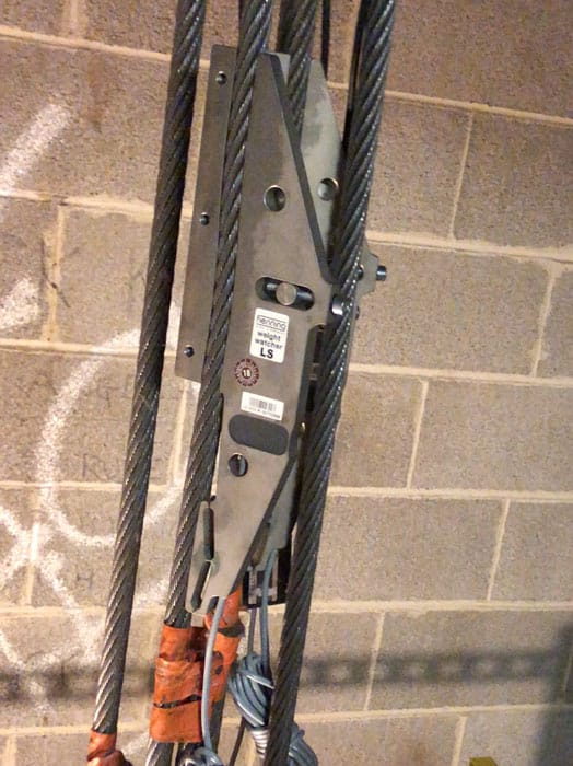
WEARwatcher measures the dynamic rope tensions, which your authors considered the first place to look for the answer. Figure 2 shows the Henning LS-1 rope gauge when examination of the issue began.
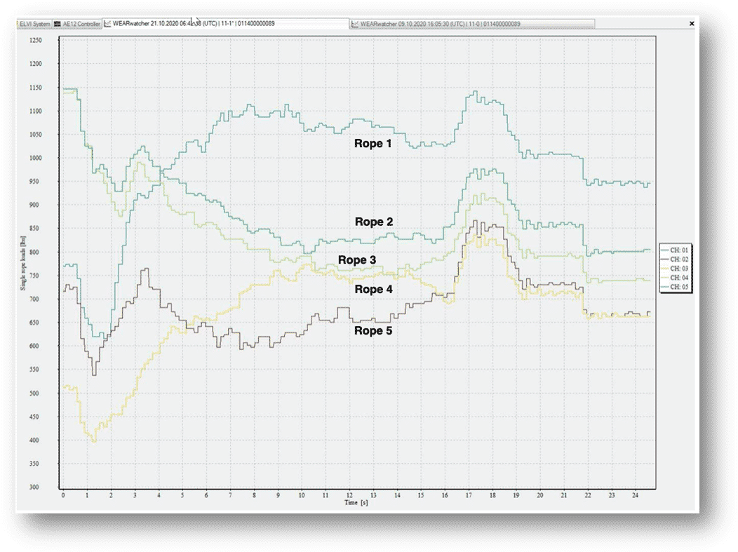
There are five ropes on the elevator, each with a Henning LS rope gauge applied. Rope gauge outputs 1-5 are assigned a color, and the five colored lines graph the dynamic change in tension during a run (Figures 3-5). Figure 3 graphs the five rope tensions through a full run. The tensions varied from 700 lb (317 kg) to 1,200 lb (544 kg) during constant travel. The difference in tension is a problem: 1,200 – 700 lb = 500 lb (277 kg) between the lowest and highest rope tensions. Suspension members (ropes) are equally tensioned when the highest tension measured is within 10% of the lowest tension measured. The A17.1-2019/B44:19 code requirement is:
“8.6.4.1.3 Equal tension shall be maintained between individual suspension members in each set. Suspension members are considered to be equally tensioned when the smallest tension measured is within 10% of the highest tension measured. When suspension member tension is checked or adjusted, an antirotation device conforming to the requirements of 2.20.9.8 shall be permitted.”
The ASME A17.1/CSA B44 Handbook on Safety Code for Elevators and Escalators — 2016, a collection of writings explaining the rationale for code requirements, elaborates:
“8.6.4.1.3 This requirement defines ‘equal tension’ in the suspension means as the lowest tension within 10% of the highest tension; 10% was found to be standard practice, and attainable. This requirement permits installation of antirotation devices conforming to 2.20.9.8 when rope tension is checked or adjusted.
“Antirotation devices are an important component of the suspension system. The need was not included in Code until the ASME A17.1-1993 edition, which included a requirement for a single, continuous loop of wire rope. However, improper tightening of the wire rope can cause shackle/rope alignment to move out of plumb. Antirotation devices are allowed as part of a replacement, provided they comply with 2.20.9.8. This requirement also permits incorporation of antirotation devices when retensioning suspension ropes.
“The necessity of maintaining uniform tension among suspension members is important to ensure maximum life of the suspension members and minimize wear of drive sheave groves. A number of instruments to check rope tension have been developed in recent years to make adjustment easier and more accurate.”
From a stopped position, the highest tension is 1,070 lb (485 kg); 10% is 107 lb (49 kg). These ropes were out of tension by 333 lb (151 kg), approximately 31%. But, during the run, at time “13.5,” rope 1 measured 1,200 lb (545 kg), and rope 5 measured 680 lb (309 kg). So, the tension differences grew larger, a difference of 520 lb, or 43%. Therefore, WEARwatcher was sending constant error messages to equalize the ropes.
During the run, the tension differences changed: ropes 1 and 2 increased tension, while ropes 3, 4 and 5 decreased tension (Figure 3). Two things to note: measurement of the rope tensions while the elevator is stopped in the hoistway cannot determine dynamic changes, providing probably the single clearest explanation of why it is sometimes impossible to equalize rope tensions on some jobs. Seeing the changing rope tensions is a breakthrough in elevator maintenance; this is something we were unable to see before.
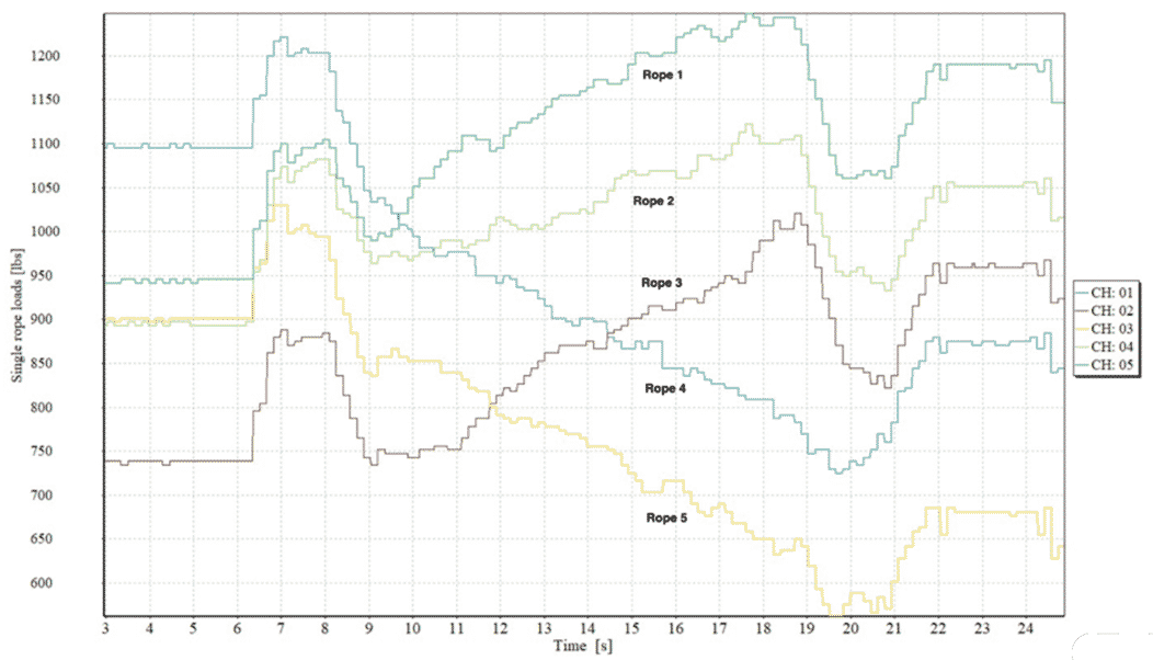
The accuracy of the gauges was called into question because the values were changing so much. To verify that the LS rope gauges were not sending out anomalous information, the maintenance contractor moved all the LS gauges to different ropes and attempted equalizing them. After this was done with the elevator at the first floor and then the car was run, there were similar unequal rope tensions again (Figure 4). The LS rope gauges were verified; they moved to ropes of different tensions as shown by the color changes in the graphs. The gauge was assigned a color, and moving it to another rope changed the rope color. In Figure 3, “brown” was on rope 1, then moved to rope 5 in Figure 4. After proving the LS rope gauges were not the problem, the next step was to concentrate efforts on equalizing the ropes. This was attempted, as shown in Figure 5.
After using traditional equalizing procedures, the resultant tensions were still very divergent after running the elevator up and down several times. Measuring the tensions, adjusting the shackles, then running the car put the ropes out of balance every time. Looking closer at the Figure 5, during this run, ropes 1, 2 and 3 show increasing tension, while ropes 4 and 5 showed decreasing tension. Looking back at Figures 3 and 4, this also documents rope tensions that increased and decreased during travel.
After analyzing the efforts to equalize the tension and seeing the plot data from WEARwatcher, it followed that the ropes could not be tensioned. So, there was something preventing equal tension. It was clear there was a change in rope tension, possibly related to the grinding of the groove material.
Diameter Reduction
Of the two traction components, reduction in diameter of a groove or rope can cause such wild swings as shown in the figures. The amount of material then becomes the significant question: how much material loss matters before the customer has to replace the sheave? Why does it occur, and what caused it?
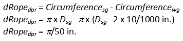
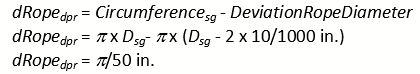
To understand this issue, the question I asked is, “What happens if one groove becomes 0.010 in. shallower in diameter?” It follows that the loss of groove material changes the circumferential distance the rope has to run on is the obvious conclusion. However, does a radius of 0.010 in. make a difference? As diameter is twice radius, Eq. (1) derives the circumferential difference of a new groove to a worn groove:
 (1)
(1)
where dRopedpr is rope distance per revolution on the sheave, Circumferencesg is circumference with standard groove, Circumferencewg is circumference with worn groove, and Dsg is the diameter of standard groove. The same equation holds true if a rope diameter loses 0.010 in.:
 (2)
(2)
For a given combination of rope and sheave, the rope length difference per traction sheave revolution, given 0.010 in. reduced diameter (sum of reduced sheave diameter and/or reduced rope diameter) is derived in Eq. (3):
![]() (3)
(3)
For a given travel height, sheave diameter and suspension ratio, we can now see the full picture of what is occurring. With the following given for the traction system in Figure 1 (travel height of 100 ft [1,200 in.], sheave diameter of 30 in. and suspension of 1:1), the total rope slip during a full-length run is the sum of the slip per revolution times the number of revolutions. First, deriving the number of revolutions:
![]() (4)
(4)
Rope length slip difference between a groove/rope with no diameter reduction and a groove/rope with 0.010 in. diameter reduction during a full run is:
![]() (5)
(5)
As one might expect, the smaller traction groove diameter (or rope diameter) requires less rope length per sheave revolution. While 0.8 in. does not seem like much for a travel height of 100 ft, let’s calculate how much this is in terms of slip force. This force causes the rope to slip traction and grind material.
Ropes behave like springs; they have a spring rate, and their behavior for equalizing forces (due to tension differences between ropes) is what we are now considering. There is a force (tension) on one side of the traction sheave going to the car (T1) and another force (tension) going to the counterweight (T2). That is the force trying to be equalized by the characteristics of a spring. The resulting force difference can be derived to determine the force that results from the rope length due to diameter differences:
![]() (6)
(6)
where ∆Fslip is change in force, which tends to cause the rope to slip over the traction groove, T1/T2; ∆l is rope length difference; and c is rope spring rate of rope. The rope‘s spring rate depends on the actual rope length:
![]() (7)
(7)
where E is the rope elongation module, A is a metallic cross-sectional area of the rope, and l is actual rope length.
The resulting difference in force, combining the equations into one, yields:
![]() (8)
(8)
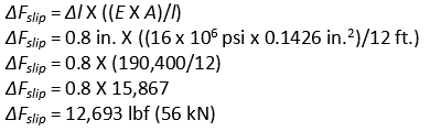
When the car is at the top landing, the rope length between traction sheave and car (1:1 suspended) is approximately 12 ft (3.7 m). Using 5/8-in. (15.8-mm) 8×19 natural fiber core ropes, the rope elongation module, E, is 16 x 106 psi (110 kN/mm²), its metallic cross-sectional area, A, is 0.143 in.2 (92.3 mm2), ∆l is the above derived rope length difference of 0.8 in. (20.3 mm), and l is the actual rope length of the already mentioned 12 ft (3.7 m).
 (9)
(9)
Equation (9) calculates 12,693 lbf (56 kN) of force is developed on one side of the sheave groove on the rope on a damaged groove or with a reduced diameter. The traction (friction) between ropes and traction sheave is a much lower force, on the order of 1,000 lbf (4.4 kN), so the rope slips over the groove, as the force of traction is considerably less than the slip force. (Rope slip is different from rope creep. Slip is when traction is lost; rope creep is made up of micromovements of a rope that occur normally during a run.)
A17.1/B44 defines creep as slight incremental, natural movement of the suspension means over their arc of contact with the driving sheave due to tractive force. The tractive force is a result of unequal tensile loads in the suspension means at points of entry and exit from the driving sheave, the tensile elasticity of the suspension member and the frictional work occurring in the direction of greater tension. Creep is independent of the motion status or direction of rotation of the driving sheave. It exists in all traction systems and is not loss of traction. It can occur while the drive sheave is stationary or rotating. It does not grind material off the sheave groove.
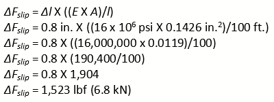
Now, let’s look at what is happening if the car is at the bottom landing: using Eq. (9) again, but inputting 100 ft for l (actual rope length), which is the elevator travel height. This results in a force difference of 1,523 lbf (6.8 kN), which still indicates a very large difference in force/tension between the ropes and is much closer to the measurements shown in Figures 3-5 (higher than the traction force, so the rope slips and actual tension measurement is, therefore, lower) due to the reduced groove depth. From this, it follows that shorter rope length develops higher slip forces. These conditions occur when the elevator is near the terminals.
Seeing the changing rope tensions is a breakthrough in elevator maintenance; this is something we were unable to see before.
 (10)
(10)
During a down run, what happens if a groove or rope has a much smaller diameter than the others? Despite the presence of an anti-rotation device (which is to prevent the ropes from unwinding, causing their length to increase), for every rotation of the traction sheave, this damaged rope/groove travels less than the other ropes. This results in increasing rope tension, because it carries more load than the other ropes until there is enough force to exceed the traction force.
During an up run, all other ropes move further per rotation of the traction sheave than the damaged rope/groove. The other ropes now carry more load, and the damaged rope/groove loses tension (“slackens off”). As the tension force difference between the traction friction force and the equalizing spring force exceeds a value, the rope slips and “equalizes.” This movement grinds the sheave material as seen in Figure 1, because the rope is much harder than the traction groove. It is literally sawing (grinding) the groove. Left unattended, it could result in complete separation of the sheave itself.
Any sign of metal particles should immediately trigger the maintenance task of equalizing the ropes.
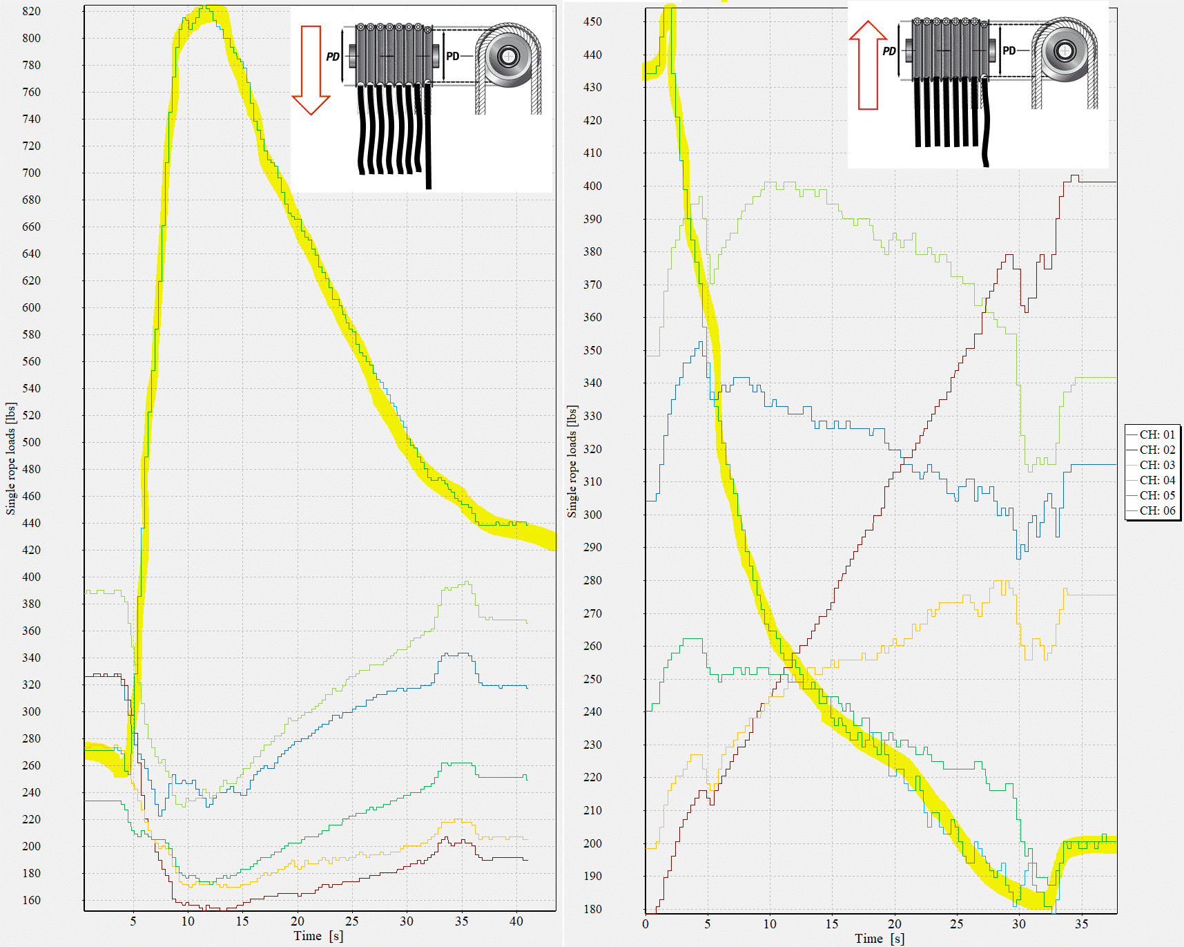
Figure 6 shows this behavior in an extreme example. The highlighted rope is from two recordings of different elevators. The increasing tension in the down run is highlighted on the left, and the decreasing tension in the up run is highlighted on the right. That variant tension causes rope slip and the much harder steel wire rope to grind sheave material as seen in Figure 1.
Checking for Diameter Reduction on a Sheave
In years past, maintenance included monitoring rope tensions. Then, practices changed, and unequal rope tension damage increased. The code added requirements for mandatory equal tensions within 10% to require this maintenance procedure. It is clear this is not an issue that can be seen with the naked eye. Therefore, inspectors can only notice particles on the ground to write a violation. Measuring the groove depth should be added to all MCPs and the inspector’s checklist. This is a simple measurement.
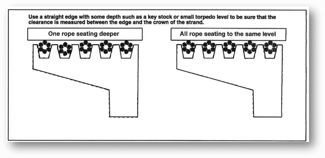
Determining the condition of the relative sheave groove depth/rope diameter is done by placing a straightedge across all the ropes at the top of the sheave (overhead driving machine) or at any point where all the ropes are fully in the grooves (Figure 7). Careful measurement for any variance in the rope crown heights will show either a rope or groove diameter difference. Where the traction sheave has grooves deeper than the outer edge of the sheave, place the straightedge, and use feeler gauges to measure if the gaps over the crown are equivalent.
Rope Equalizing Tools
The marketplace has equalizing tools that can ease the task of rope equalization. These tools incorporate individual rope hydraulic pressure cylinders, which allow rope lengths to vary, proportional to the individual cylinder pressures, to adjust the shackle nuts in real time. One such system is Brugg Lifting’s Rope Load Equalizer. Additionally, WEARwatcher has visible displays of rope gauge tensions for ease of adjusting rope tensions.
Conclusion
In Figure 1, this elevator’s rope tension differences began a destructive course when the first material began grinding off the sheave groove due to unequally tensioned steel wire ropes. This was caused by maladjustment of the fastening, reduced rope diameter and reduced traction groove diameter. This loss of material then further prevents equalizing the rope tensions, further damaging the sheave groove. The initial culprit was unequal rope tensions from turnover, then never checking them again, then (even worse) seeing the ground particle material under the machine and still not correcting it. Proper maintenance should have been performed to verify 10% tension annually and adjust the rope tensions and measure the groove depths.
The lesson here is that any sign of metal particles should immediately trigger the maintenance task of equalizing the ropes. If 10% or less cannot be achieved, an examination of the groove depth and rope diameter must be done, and appropriate actions, such as regrooving (if possible) or (in the worst case) replacing the sheave, must be taken. It is not that material properties have changed, as some have assumed; steel and steel wire ropes today are the same as they were 50 years ago. Equalization of ropes and measurement of rope and groove diameter is a maintenance task that must be done with regularity to keep the system performing safely and ensure full design life.
Learning-Reinforcement Questions
- Use the below learning-reinforcement questions to study for the Continuing Education Assessment Exam available online at Elevator Books or on p. 129 of this issue.
- What are reasons why it is challenging to determine responsibility for causing and repairing sheave damage?
- Why are rope gauges critical tools in suspension system maintenance?
- Why may it be important to consult the ASME A17.1/CSA B44 Handbook on Safety Code for Elevators and Escalators?
- What are the differences between rope slip and rope creep, and which is the one for which concern is warranted? Why?
- How often must equalization of ropes and measurement of rope and groove diameter be done to keep an elevator system performing safely and ensure full design life?
Tim Ebeling has been employed as head of development with Henning GmbH & Co. KG since 2003. In this capacity, he established the R&D center in Braunschweig, Germany. A team of employees is now working there on the development and production of electronic and measurement components for lifts. Since 2012, he has also been managing director. A particular focus of his is measurement technology, an area with which he has many years of experience developing acceleration and rope-load measuring systems.

Get more of Elevator World. Sign up for our free e-newsletter.


