Inspection of Elevator Ropes, Part One
Dec 1, 2020
Conditions to look for and procedures to check when checking rope replacement criteria and other suspension-connected issues

Value: 1 contact hour (0.1 CEU)
This article is approved for Continuing Education by NAEC for CET® and CAT®.
EW Continuing Education is currently approved in the following states: AL, AR, FL, GA, IL, IN, KY, MD, MO, MS, MT, OK, PA, VA, VT, WV and WI. Please check for specific course verification of approval at Elevator Books.
Learning Objectives
In this article, you will learn:
- Which suspension means standard is mandated by AHJs in the U.S.
- The background and intention of the suspension means standard
- What rouge is and what it is not
- When a rope should be replaced
- The process of rope replacement
This article is based on a January 2020 presentation by your author at the fourth-annual Alberta Elevator Industry Seminar, which was sponsored by Alberta Elevating Devices and Amusement Rides Safety Association. The title of that presentation was “Inspection of Elevator Ropes. And a Few Other ‘Rope-Connected’ Issues.” . . . Editor
At almost every industry training-related meeting, a first requirement is that sessions begin with and focus on material related to the elevator safety standard. In that spirit, this article emphasizes inspecting and assessing the condition of suspension means (mainly ropes, though “noncircular elastomeric coated steel suspension members” [belts] and aramid fiber elevator ropes are also part of the standard). A good complement to rope inspection is a summary of some continuing rope-related issues and a tie-in to some tools that are now providing solutions for longstanding and persistent rope failure and wear issues.
ASME A17.6-2010: Elevator Suspension, Compensation, and Governor Systems was published by the American Society of Mechanical Engineers (ASME). This standard is a relatively new addition to the series. It was developed over a few years by the Suspension Means Task Group (SMTG): a subcommittee of a key group, the Mechanical Design Committee. We are fortunate to have a group of interested individuals, mostly technical experts, who give their time to ASME. Those who become involved with this group will be informed by one of the “old hands” of the difference between codes and “The Standard(s).” In decades prior to 2010, there were already several regulations (rules, guidelines, and standards) in our industry directed at how ropes (suspension means) are to be inspected. In some cases, there was a little about the care they should get. References and guidelines about elevator ropes can still be found in the appendices of ASME A17.1/CSA B44 Section 8, and ASME A17.2: Guide for Inspections of Elevators, Escalators and Moving Walks Section 3.23. Our industry standards are, by design and intent, performance-based, and effort is made for them to not be prescriptive.
It is important to include some explanation of how to talk about our industry standards in an article like this. It is acceptable to cite related sections of standards and refer the reader to them. It is important to note that, though an article will avoid copying printed sections of parts of the standards, it is not to be assumed that all their details are being covered here. This article neither claims to be complete, nor fully accurate with respect to meeting all code requirements. If it is used as a reference, no assumption should be made that material from the latest and most appropriate code revision is included. Service providers in our industry are required to get and have copies of relevant standards and appropriate revisions when inspecting elevators. Independent writing and descriptions will not take the place of that. The goal of this article is to give the reader some overview of important issues and concepts and, hopefully, some good ideas.
Taking a specific and deep enough look into the A17.6 standard, we can immediately learn (from the preface) that this standard was created to cover the “means and members of suspension, compensation and governor systems for Elevators” within this relatively new standard (recognized and published in 2010). It details material properties, design, testing, inspection and replacement criteria for these means and includes steel wire rope, aramid fiber and noncircular elastomeric coated steel suspension means. The new standard proposes to cover existing and known designs and technology and set a foundation for potential new designs. The SMTG took a few years to produce this standard. The SMTG considered already existing rules and guidelines on elevator ropes in A17.1 (as noted), the A17.2 Guide for the Inspection of Elevators, Escalators and Moving Walks and the A17.3 Safety Code for Existing Elevators and Escalators.
Supporting a clear understanding of ropes and other newer technology as “suspension means,” the A17.6 standard covers (nearly) all of the basic terminology, design issues and rope structure, as well as materials and grades (in terms of strength), and even suggests some structure with respect to quality systems by manufacturers. Basic information is set out with the goal to “provide safe and consistent criteria” for suspension members. Leading up to the release of A17.6, experiences before 2000 with ropes in the field suggested a need for consistency. Many rope suppliers were also involved with this effort. Sections 1.3 through 1.9 of this standard cover terminology, definitions, concepts, mechanical properties, workmanship, dimensions, tolerance, ordering requirements, ordering, packaging and identification.
This article will focus on A17.6 Section 1.10, which covers the process of inspection of steel wire elevator ropes: identifying and understanding replacement criteria. A good general understanding of wear and fatigue on wire ropes will inform the inspector to make a concentrated inspection on the most used (working) section of rope, which is the part of the rope that is bending the most while under traction load. First, identify the common landing for the elevator being inspected. This is typically either the bottom landing or lobby floor. With the car parked there, mark the ropes in the machine room with a visible chalk or crayon 2-3 ft ahead of and after the drive sheave. Consider here whether today’s control systems are sophisticated enough for us to make a digital marker of that place. Perhaps we could then have the elevator drive to exactly that place in the hoistway where the inspector could stand on top of the car and look directly at and inspect that most-used section.
This identified and marked 6-10-ft section of rope is where to concentrate the inspection: if indications for replacement are to be found, they will likely be here. When there is wear and fatigue that can be seen, it can be expected to show first in that most used (working section) of the suspension rope. However, if nothing is found, a visual check of the rest of the rope length should still be made for visible damage, adverse surface conditions (such as rust on rope), kinks in ropes, whether the ropes are correctly shackled and affixed, and whether an
anti-rotation cable is in place.
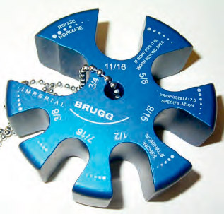
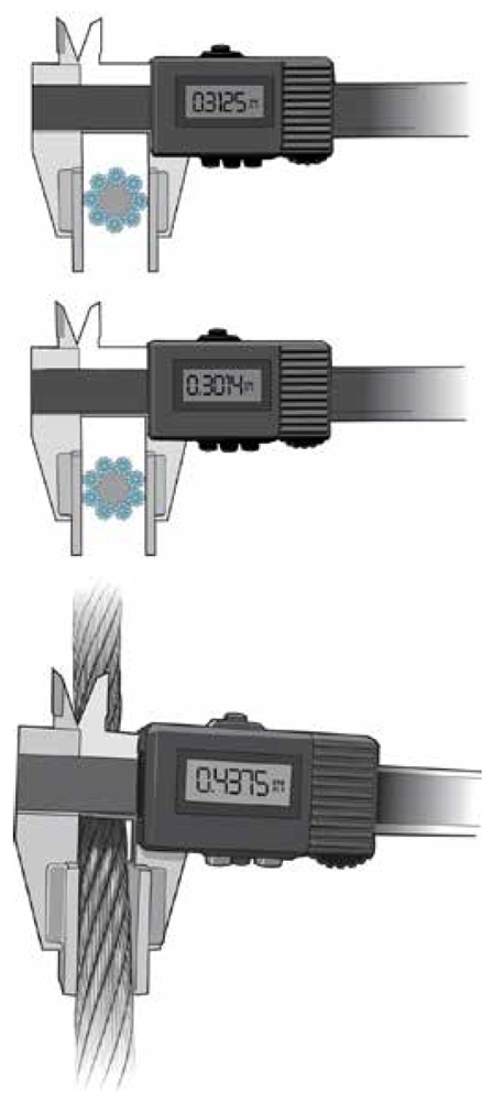
After marking the “key” section/rope area, get on top of the car, take measurements of rope diameters in that section (or use a rope go/no-go gauge). During and after the diameter check, break/fatigue conditions that indicate replacement criteria in the standard should be inspected.
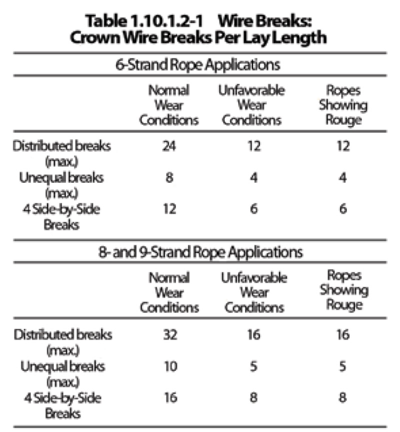
A few important terms in the standard related to inspecting installed suspension ropes and assuring they are safe at the time of inspection is in order. First, in “normal wear” conditions, ropes with diameter of 8 mm or less are permitted to have diameter reduction of up to 3.125% of their diameter. Ropes exceeding 8 mm in diameter are permitted to have a maximum diameter reduction of 6.25%. Ropes in “unfavorable wear” conditions are permitted those same diameter reduction percentages, but the number of crown wire breaks is reduced by half. “Unfavorable wear” is explained some in the “GENERAL NOTES” to Table 1.10.1.2-1 (Table 1) and Section 1.10.1.2 (d). For “unfavorable wear,” we find that the standard mentions the existence of reverse bends, ropes installed on nonmetallic, coated plastic or fiber-reinforced sheaves or on sheaves with liners or inserts (as there is increased concern for valley brakes when there is nonmetallic contact), corrosion issues, unequal loading, torsion and poor sheave grooves. Giving these “conditions” a little more notice and thought may open rope inspections to deeper consideration and, perhaps, a better understanding of fatigue and wear factors.
Rouge
Rouge is a type of rust (or internal oxidation) generated by internal nicking and notching of wires inside rope strands or between strands. Rouge is seen coming from inside the rope itself, typically as a red/orange paste or as dust coming from inside the rope. Another look at Table 1.10.1.2-1 and into the balance of Section 1.10 make the importance at inspection of looking for rouging in ropes or discovering valley breaks evident. The existence of rope rouge is significant at rope inspection, as it reduces permitted diameter reduction to half (from 6.25% to 3.125% in ropes larger than 8 mm) and indicates immediate failure if found on ropes with diameters 8 mm or less. Rouge also cuts the crown wire break numbers in half.
Before concluding a discussion of rouge, it is important to also describe what rouge is not. There has been a misunderstanding by some that surface rust (caused by water or moisture on a rope) might be rouge. There have also been situations where the sheave groove is relatively softer than the ropes. In these cases, the sheave itself sheds particles of iron or steel, which then oxidize, causing a suspension of red dust in the air. This dust can also be seen collecting on equipment in the machine room. Neither of these occurrences are rouge and, thus, do not trigger more aggressive inspection under the “Ropes Showing Rouge” guideline.
Breaks
Valley breaks (wire breaking below the crown at sides of wires that do not touch the sheave) are also, like rouge, a signal of internal (and invisible) problems with a rope. Consequently, Section 1.10.1.2 (f) and (g) require that a rope fails if there is more than one valley break in any lay length on the rope and if there is just one valley break in a lay where rouge is present.


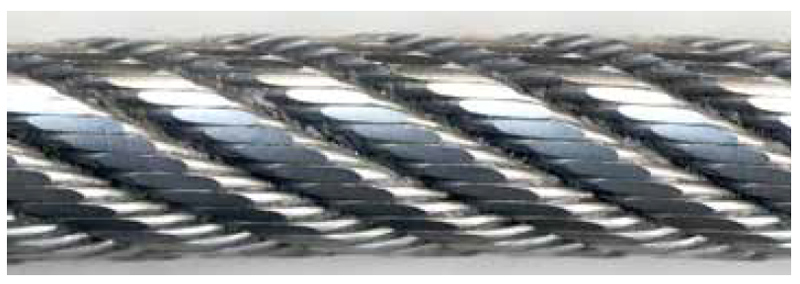
Separate from diameter reduction, broken wires are the physical indication and result of bending fatigue. There are three different types of crown wire breaks an inspector needs to recognize (Figures 5-7):
- Randomly/equally distributed, in which the number of breaks in a lay in the worst section exceeds the numbers shown in
“Normal Wear Conditions” - Unequal/concentrated wire breaks in one or two strands of one lay that exceeds the numbers shown in “Normal Wear Conditions”
- Four side-by-side wire breaks in total, exceeding the numbers shown in “Normal Wear Conditions.” When there are “Unfavorable Wear Conditions” or rouge is present, the maximum numbers of allowed wire breaks for each of the three types are reduced to half.


Replacement
Any of the inspection criteria detailed in ASME A17.6-2010 being met indicates that the full rope set needs to be replaced. The timing and urgency of rope replacement is a process handled between the AHJ and elevator service provider. Finding just one of the proscribed conditions on one rope normally suggests there is some time to arrange and schedule a rope replacement for that elevator. Some AHJs may issue an order after inspection and allow up to 60 or 90 days for the replacement to be completed. If ropes are found to have multiple or many replacement critera met across multiple ropes during inspection, the decision by the AHJ and/or service provider may be to shut the elevator down and order immediate rope replacement. This part of the process is important and should be discussed and determined onsite.
Specifics
The standard has some specific requirements worth noting and knowing. ASME A17.6-2010 Section 1.10.3 includes specifics about measuring rope diameter during inspection: “Measurement for diameter shall be taken on a straight portion of rope at the worst location. Two measurements at the same position at right angles shall be taken. . . . Ropes shall be replaced if both of these measurements are below the replacement value. . . . If only one of the measurements is below the replacement value, then the criteria for wire breaks under ‘Unfavorable Wear Conditions’ shall apply. See Table 1.10.1.2-1.” This measurement can be done with a good set of (calibrated) calipers or by using a go/no-go gauge. The portion of a rope go/no-go gauge appropriate to the diameter of the rope being checked should not fit over it. If the gauge fits on the rope size indicated, the maximum permitted reduction has been surpassed. There are also gauges designed to measure half-step reduction if rouge is present. If using one, ensure that the gauge has been designed and manufactured to meet A17.6-2010 (or later, as appropriate). Changes made to the diameter-reduction table in A17.6 reflect consistent percentage reductions. Older gauges, instead, reflected variant percentages. So, rope go/no-go gauges designed or made before this standard was published may not be compliant to the diameter and rouge requirements.
A17.6-2010 Section 1.10.3 reads, “Replacement of all ropes, except governor ropes (see ASME A17.1/CSA B44, requirement 8.6.3.4), shall conform to the requirements of 1.10.4.1 through 1.10.4.6.” Most of these six requirements are worth thinking about here. The first section, of course, indicates that replacement ropes shall be as specified by the OEM (detailed on the crosshead data plate) or be at least equivalent in strength, weight and design. This last statement is important, because there are now “equivalent” ropes available. Particularly, there are ropes with nine strands that are superior for more demanding elevator systems than the original ropes used.
Part 1.10.4.2 of this section says that ropes that have “previously been installed and used on another installation shall not be reused.” Part 1.10.4.3 sets out that all ropes in a set shall be replaced, except as permitted by 1.10.5, which indicates:
“If one rope of a set is worn or damaged and requires replacement, the entire set of ropes shall be replaced; except, where one rope has been damaged during installation or acceptance testing prior to being subjected to elevator service, it shall be permissible to replace a single damaged rope with a new rope provided that the requirements of 1.10.4.4 and 1.10.5.1 through 1.10.5.1.6 are met. Damage includes but is not limited to kinked ropes.”
Further, “. . .the suspension ropes, including the damaged ope, shall not have been shortened since their original installation.” The other sections cover the requirements of rope data tags, as well as proper rope fastenings conforming to ASME A17.1/CSA B44 Requirement 2.20.9.
This standard also introduced the concept of a remaining residual strength requirement of 60% of a steel rope or the other two suspension means (aramid rope or noncircular elastomeric coated steel strands). This requirement perhaps suggests evidence through extensive bending fatigue testing exists to certify there is more than 60% of residual strength in these suspension means until the time the means needs to be replaced. Such a requirement is necessary for suspension means for which one cannot visually inspect if there is wear or degradation. The concept is continuing to be discussed in ASME code committees, including the Mechanical Design Committee.
In A17.6-2010 Section 1.10.1.2.1 for steel ropes, it states that “the rope manufacturer and considering the application, shall establish the design life limit to ensure that the residual strength of wire ropes less than 8 mm (0.315 in.) diameter is not less than 60% of the minimum breaking force at the time of replacement.” There is similar language for the other two types of accepted suspension means in Sections 2.9.4 and 3.7.4.
Conclusion
In the past, there was a requirement that a set of ropes for an elevator installation (original or replacement) needed to be not only the same diameter, type and design from the same manufacturer, but also from the same reel or manufacturing run. That requirement was eliminated in the code prior to the publication of A17.6-2010. It remains clear that the ropes in a set “shall be new, all from the same manufacturer and of the same material, grade, construction, and diameter” (from Section 1.10.4.4).
The old requirement for ropes to come from the same manufactured reel (or even from the same production lot number) was an onerous and unnecessary cost that also caused long delays in getting replacement ropes. Experience has shown that when the rope is the same type and diameter and comes from the same manufacturer (even from different manufacturing lots), the design (lay lengths) and manufacturing process (including the manufacturer’s machines and materials) are the same and controlled. Since that determination has been made, it has been observed that the ropes are compatible and will work together as a set. This has been well established and proven by supply to many thousands of elevator installations.
With an understanding of the inspection of ropes and the criteria for their replacement, a logical next thought would be, “What causes wear and fatigue of ropes (suspension means)?Which factors are involved, and what can we do, if anything, to manage and reduce that progress of wear and fatigue failure?This is a cost-control opportunity that should favor and interest elevator owners and those providing service. A future article covering the causes of increased rope failure and what accelerates the need for replacement is planned. We have known about all the factors for many years now. What we were missing was tools and systems that present and support an effective strategy for the care and safety of suspension means.
Learning-Reinforcement Questions
Use the below learning-reinforcement questions to study for the Continuing Education Assessment Exam available online at Elevator Books or on p. 126 of this issue.
- Which references should any inspector possess?
- What is the importance of the modern standard on suspension means?
- Which methods of determining whether ropes should be replaced are acceptable?
- How may sheave wear be determined when examining suspected rouge in a suspension means?
- How might the advancement of technology and data gathering in the industry affect rope requirements in the future?
Also read: Inspection of Elevator Ropes, Part Two
Get more of Elevator World. Sign up for our free e-newsletter.


